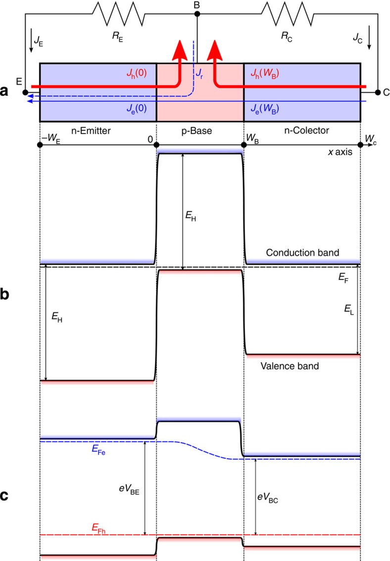
Figure 1. Structure of the three-terminal heterojunction bipolar transistor solar cell.
Simplified layer structure showing also electron (blue) and hole (red) current densities with sign criterion that current densities are positive when flowing in the direction indicated by the arrow (a). Simplified bandgap diagram in equilibrium (b). Simplified diagram under conditions in which the cell is delivering electrical power (c). EFe and EFh are the electron and hole quasi-Fermi levels.

