
Figure 1.
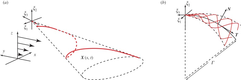
Reference frames and flagellar waveforms. A schematic illustrating the flagellar waveforms together with the reference frames. (a) The flagellar reference frame, which is right-handed, and a typical symmetric elliptical helicoid flagellar profile, as depicted in red, with X(s, t) denoting the position in the laboratory reference frame for the location at time t and arclength s along the flagellum from the origin of the flagellar reference frame, ξ = 0. The background shear flow is also depicted relative to the laboratory reference frame, x. (b) The asymmetric flagellar waveform. The centreline of a curvilinear elliptical cone is the arc of a circle of radius Γ, with unit tangent T, unit normal N and, not depicted, unit binormal  . The flagellar wave forms a helix on this cone at any snapshot of time, with the flagellum at three different snapshots of time illustrated in red. For both (a) and (b), the time evolution of the flagellum profile corresponds to a wave propagating on the cone, away from the origin of the flagellum reference frame, ξ = 0. (Online version in colour.)