
Fig. 1.
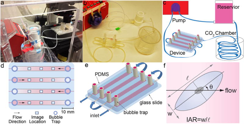
(a) Flow system assembled on the microscope stage in the live cell chamber. (b) Flow system assembled on a lab bench. (c) Schematic illustration of the flow system. (d) Schematic illustration of the device showing imaging locations. (e) Schematic illustration of the microfluidic flow device. (f) Morphological parameters include: orientation angle with respect to the flow direction (θ), inverse aspect ratio (IAR) defined as the length of the short axis (w) divided by the length of the long axis (ℓ).