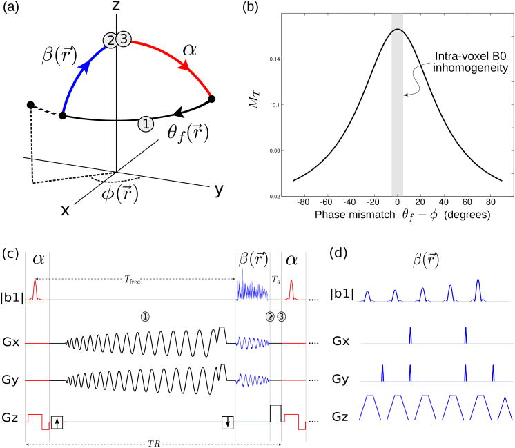
Figure 1.
Proposed STFR functional imaging sequence. (a) Steady-state spin path for a single spin isochromat. The tip-up pulse (blue) is tailored to the local free precession angle. In general, there will be a mismatch θf –φ between the spin phase at the end of the free precession interval (θf), and the phase (direction) of the tip-up pulse (φ). In STFR imaging, the goal is to design a tip-up pulse that minimizes θf –φ within the ROI. (b) Steady-state STFR transverse magnetization for a single spin isochromat as a function of phase mismatch θf –φ, calculated from Eq. [2]. The observed voxel-averaged signal is obtained by weighted integration of the signal profile over the B0 distribution within a voxel (Eq. [3], illustrated with shaded gray column). (c) Pulse sequence diagram for the STFR sequence used in the in vivo functional experiments (spiral tip-up pulse). (d) fast-kz tailored tip-up pulse (only 5 subpulses are shown).

