
Fig 2. The wired racks with parts attached to the racks.
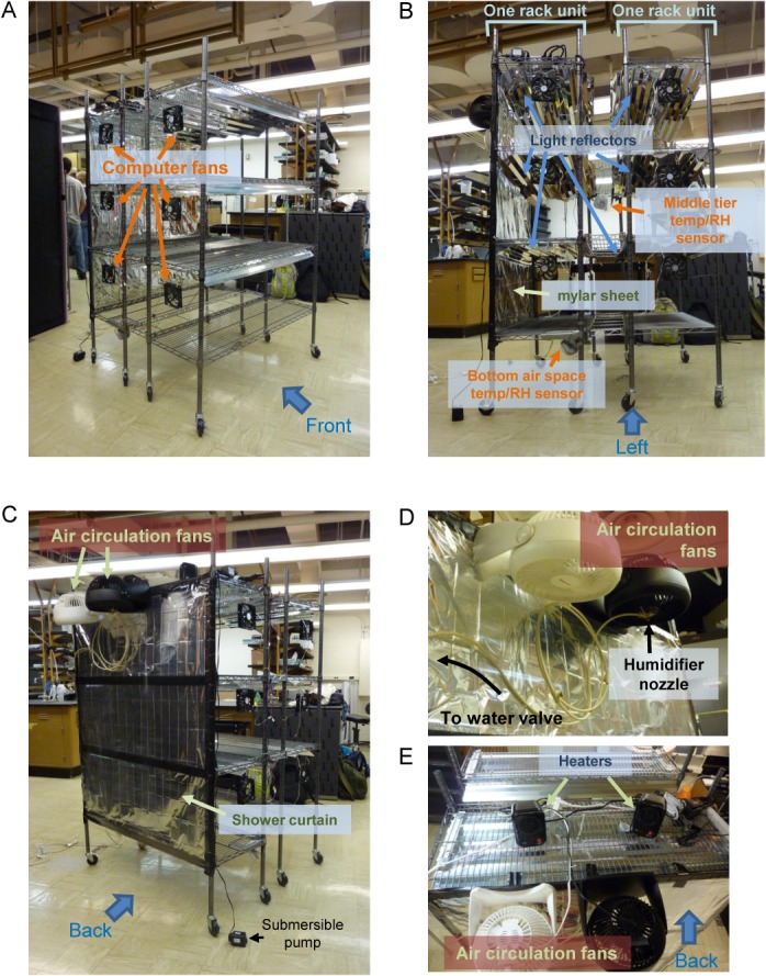
A. View from the front left corner; B. View from the left side; C. View from the back left corner. The wired racks and the attached parts were fully assembled outside the growth tent and then rolled into the tent, with the exception of four parts: three narrow shelves connecting the two rack units and the middle growth tier sensor that was hung from the top narrow shelf were inserted once the racks were in the tent. Once the racks were in the tent, the drainage system then assembled in the tent. Note that the submersible pump that was placed inside the plastic tub in the bottom air space is shown loose on the floor in these photographs. Then the narrow shelves and the middle growth tier sensors were attached, and electrical wiring, including wiring for the lights, was finished. D. Close up view of the humidifier nozzle and air circulation fans. The fans were attached to the top of the air mixing space in the back of the chamber; this space is separated from the growth space by a Mylar sheet and a shower curtain liner as shown in B and C. E. Top view of the racks, taken from the back. Two desktop heaters were placed on top of the racks to provide compensating heat when the lights were off (these are the night-time compensation heaters). Power adaptors for the computer fans (shown in A), the temperature/RH sensors (shown in B), and the submersible pump (shown in C) were also placed on the top shelf of the rear rack unit; these components are partly seen on the right side of the figure.