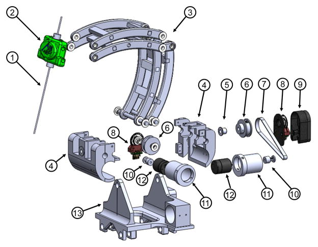
Fig. 4.
Exploded view of the RCM orientation module, showing (1) instrument/electrode, (2) headstock with cannula guide, (3) parallel linkage mechanism, (4) manipulator base frame, (5) flange bearings, (6) pulleys, (7) timing belts, (8) rotary encoders, (9) encoder housings, (10) pulleys, (11) eccentric locking collars, (12) rotary piezoelectric motors, (13) manipulator base.

