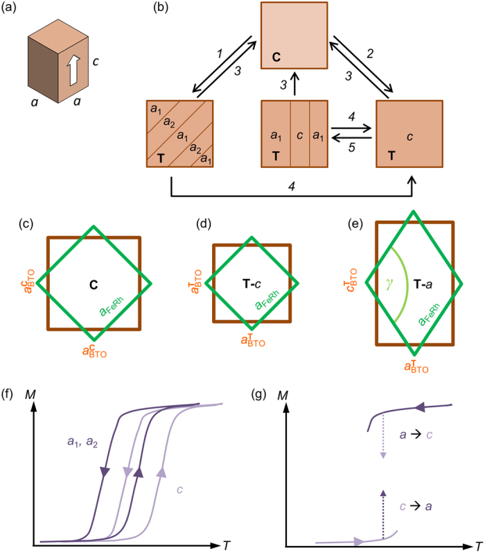
Figure 1. Experiment concept sketches.

(a) 3D sketch of the unit cell shape of tetragonal BTO. A white arrow indicates the polarization direction. (b) 2D projection of ferroelastic domains on the BTO (001)C surface: crystal phase [C = cubic; T = tetragonal] and tetragonal ferroelastic domain orientations [(a1, a2) = a-domains; c = c-domains]. Arrows indicate operations that convert between the observed domain states: 1-cool through TC without voltage V; 2-cool through TC in applied V; 3-heat through TC; 4-apply V; 5-remove applied V. (c-e) Overlaid unit cell shapes of FeRh (green) and BTO (brown) for (c) cubic BTO, and (d) c-domains and (e) a-domains of tetragonal BTO. (f) Sketch of the expected magnetization (M) versus temperature (T) for a strained FeRh film on c-domains and a-domains of tetragonal BTO. (g) Proposed experiments for large magnetoelectric effects: heat (cool) FeRh from low (high) temperature on BTO c-domains (a-domains), then transform BTO to a-domains (c-domains) to obtain a large increase (decrease) of magnetization.
