
Fig 8. Fast-slow decomposition of the model dynamics when the inhibitory V0D pathways are deleted.
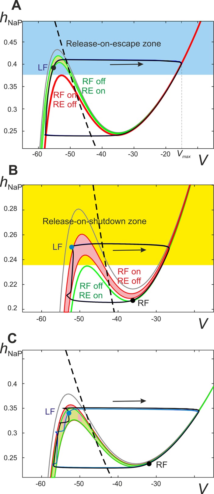
Projection of the phase portrait of the model onto the (V, h NaP) plane at α < X6. Sample positions, or image points, of flexor centers are depicted by the black (RF) and blue (LF) circles. A. Input from the right extensor center (RE) to the left flexor centers (LF) is represented as a sleeve of nullclines ranging from the maximal RE activity (lowest green nullcline) to minimal RE activity (highest green nullcline). The maximal and minimal RE activities occur at the beginning and end of the RF inactive phase, respectively. The red nullcline represents the maximal excitation to the LF from the RF when the RF is active (labeled as “RF on/RE off”). This maximum occurs immediately after the RF activates and begins to excite the LF via the V3 connection. Hence, for any of the LF's initial conditions above the left knee of the red nullcline (the blue area) the activation of the RF will immediately result in activation of the LF as well (release-on-escape). For low enough values of α the left knee of the green band is higher than the left knee of the red nullcline. This makes it possible for the LF to climb high enough during the inactive phase of the RF to find itself in the blue area by the time of escape of the latter. Once the RF activates, the LF activates as well thus stabilizing the regime of synchronous oscillations. B. α > X8 the red and green nullclines interchange their positions so that the left knee of the red band is now higher than the left knee of the green nullcline. Accordingly, it is no longer possible for the LF to get above the left knee of the low red nullcline, while moving along the left branch of the green nullcline, thus making the release-on-escape mechanism impossible and excluding synchronized behavior (see Fig 7B). Instead, such a configuration enables the release-on-shutdown mechanism, because starting at initial conditions above the left knee of the green nullcline (the yellow area) the LF immediately activates upon the deactivation of the RF. Symmetric alternation (Δφ = 0.5) is stabilized by the release-on-shutdown mechanism given that each flexor center’s image point climbs high enough along the left branch of the red band before the contralateral flexor center deactivates. C. Overlap of the flexor and extensor center nullcline bands is denoted with a checkered pattern and underlies the bistability observed in the diagram “Phase dif. LF-RF” in Fig 7B. This specific scenario corresponds to the area between X6 and X7 where flexor center synchronization co-exists with alternation in a manner dependent on the system’s initial conditions. Because of the large overlap of the nullcline bands both the escape-on-release and escape-on-shutdown mechanisms are possible (see text for more detailed description).