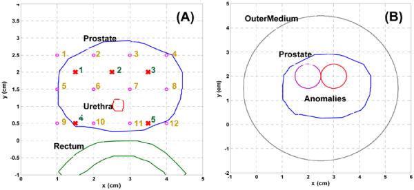
Fig. 4.

(A) Layout of prostate, urethea, and rectum contour, and source and detector locations. Circle and cross symbol represent the locations of isotropic detector and linear source, respectively. (B) shows a layout of two anomalies inserted into the prostate, and an extra outer medium is applied to surround the prostate.
