
Figure 2. Experimental considerations for 3D Bragg ptychography: beam profile and Bragg diffraction geometry.
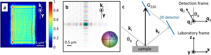
(a) Intensity pattern of the over-focused direct beam (arbitrary units)
measured with a high-resolution camera. (b) Color rendition of the
complex-valued beam profile, retrieved from the inversion of (a) and shown
in the Fresnel zone plate focal plane. The brightness and color correspond
to the linear scale amplitude  and
to the phase
and
to the phase  , respectively. (c)
Description of the 3D Bragg diffraction geometry, including the Bragg angle
(
, respectively. (c)
Description of the 3D Bragg diffraction geometry, including the Bragg angle
( ), the incident and exit wave
vectors (
), the incident and exit wave
vectors ( , respectively) and the
Bragg vector (
, respectively) and the
Bragg vector ( ). The 3D
non-orthogonal (
). The 3D
non-orthogonal ( ) detection frame
is defined in agreement with the detection acquisition modality,
corresponding to the 2D detector plane and to the rocking curve direction.
The (
) detection frame
is defined in agreement with the detection acquisition modality,
corresponding to the 2D detector plane and to the rocking curve direction.
The ( ) laboratory frame is also
shown.
) laboratory frame is also
shown.