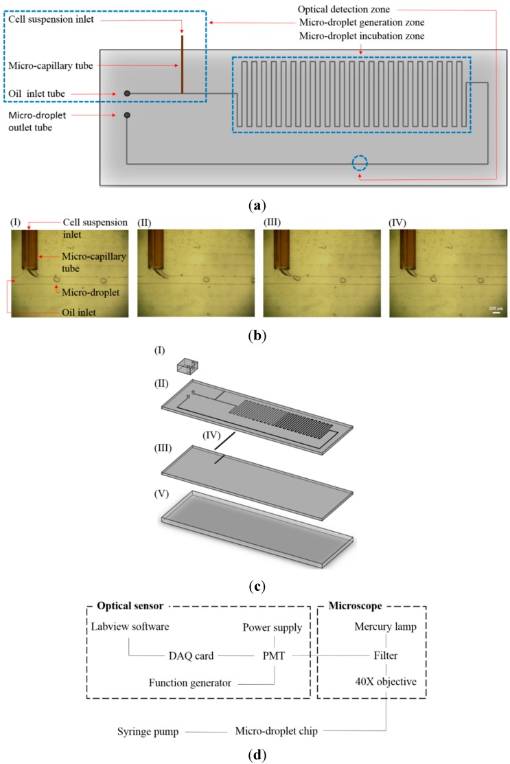
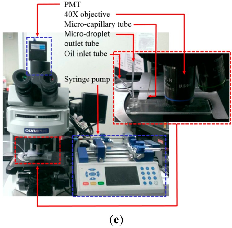
Figure 1.
(a) Schematic illustration of the microfluidic device (Top-view layout); (b) The photographs of the continuous micro-droplet generation process ((I)-(IV)); (c) Schematic illustration of the assembly of the microfluidic device ((I)-(III): microfabricated PDMS layers, (IV): micro-capillary tube, (V): glass layer); (d) schematic illustration; and (e) photograph of overall experimental setup.


