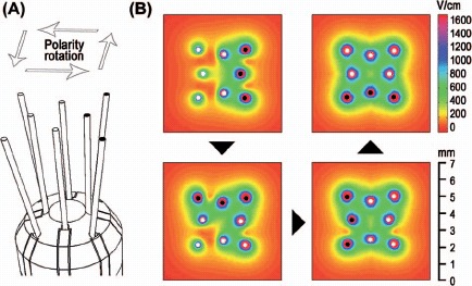
Figure 2.

The electrode device and electric field distribution: (A) The rat brain electrode device: four parallel inner electrodes and four slightly angled outer electrodes of length 5 mm. Only the distal 3 mm of the electrodes were electrically conductive. Each electrode was 0.2 mm in diameter. The electrodes had a palladium core and 35N LT coating. (B) Four polarity configurations were used to expose the region symmetrically (top view). The electric field distribution corresponding to an initial electrode polarization is shown in the top left window. The next electric field distribution (after 90° rotation of the polarity) is combined with the previous electric field distribution and shown in the bottom left window. This is repeated at 180° and 270° rotations of the polarity configuration. The electric field distributions are at depth z = 3.5 mm (see Figure 3) and shown for 100 V. White and black marks at the tip of the electrodes indicate opposing polarities.
