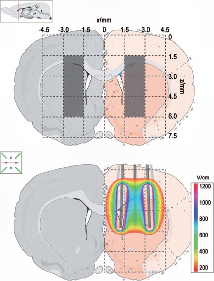
Figure 3.

Regions of interest (ROI) and the location of the electrodes: The electroporated region is defined as x = [1.5;3.0] and z = [1.5;6.0] in the right hemispheres, and the control region is defined as x = [-3.0;-1.5] and z = [1.5;6.0] in the left hemisphere. The electric field overlay (200 V) on the coronal plane corresponding to the center of the electrode device is shown in the bottom.
