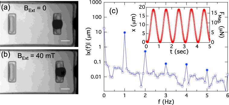
Fig. 5.

(a) MMT viewed through a lid device. The Ni sphere appears as a dark circle on the right-hand pillar. The tip of the Ni bar is visible at right. (b) Application of BExt = 40 mT deflects the magnetic pillar 30 μm to the right. Scale bars in (a) and (b) are 100 μm. (c) Inset: Motion of a magnetic pillar in response to a sinusoidal driving field BExt = B0 sin(2πft), with B0 = 20 mT and f = 0.5 Hz. Frequency doubling produces a 1 Hz response, as discussed in the text. Right hand scale shows FMag as determined from the pillar spring constant k = 0.9 μN/μm. (c) Main panel: Fourier spectrum of motion shown in inset (calculated over 10 periods). Harmonics of 1 Hz fundamental are shown as solid points.
