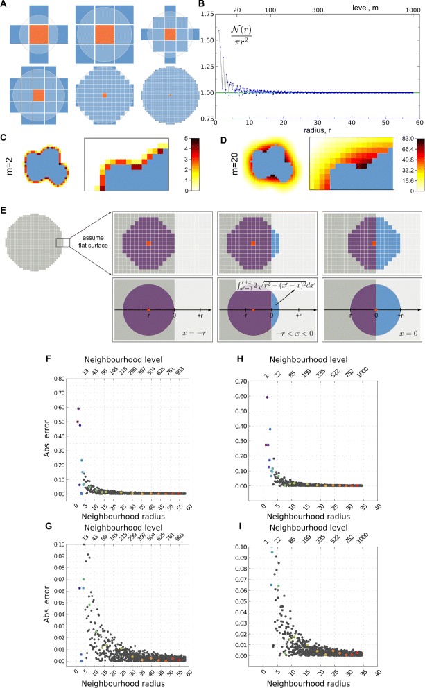
Figure 4.

Perimeter determination in a lattice-based environment like CPM.(A) Examples of neighbourhoods. From left to right, top to bottom: von Neumann neighbourhood (m=1), Moore neighbourhood (m=2), third-, fourth-, twentieth- and hundredth-level neighbourhoods. Orange site indicates origin, neighbourhood (sites in blue) is determined by the neighbourhood radius (light blue circle). (B) Lattice points within a certain radius, relative to the expected area of a circle, as a function of neighbourhood radius. m indexes the corresponding neighbourhood levels. (C, D) Cell neighbouring regions used for perimeter-related computations in the CPM, for neighbourhood levels m=2(C) and m=20(D). Colour gradients denote the number of times neighbouring lattice points are taken into account in the perimeter computation. (E) The CPM cell perimeter in 2D (or surface area in 3D) is calculated by summing all lattice points falling within the given neighbourhood which have a different state (blue lattice points) than that of the cell (grey lattice points), for all lattice sites of the cell (red lattice points). The upper row illustrates the discrete process as is performed in a CPM simulation, while the lower row illustrates the continuous approximation of this process. (F–I) Precision of the CPM perimeter correction factor ξ depends on the neighbourhood level used in the CPM simulations. The graphs show the fractional difference between the numerical and analytical estimate of ξ as a function of the neighbourhood radius. (F, G) 2D numerical estimate compared with Eq. 29. (H, I) 3D numerical estimate compared with Eq. 33. For the numerical estimates a flat cell boundary is used with increasing neighbourhood levels, from 1 to 1,000. (G) and (I) are magnifications of (F) and (H), respectively.
