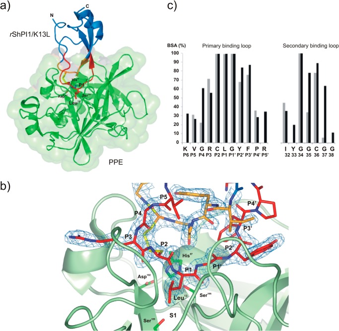
FIGURE 1.
Structure of the rShPI-1/K13L·PPE complex (PDB code 3UOU). a, schematic model of the overall structure of the complex between PPE (green, surface representation) and rShPI-1/K13L (blue), showing the changed P1 residue Leu13 of the inhibitor in stick representation. The primary (P6-P5′ sites) and secondary binding loops are highlighted in red and orange, respectively, and the linking disulfide bridge, Cys12–Cys36, is shown in yellow. b, close view of the entire complex interface centered on the S1 pocket of PPE, illustrating the formation of an antiparallel β-sheet by the inhibitor loops within the concave binding pocket of the enzyme that is typical for canonical inhibitors. The binding loops of rShPI-1/K13L (stick representation) are well defined by the 2Fo − Fc map (blue) countered at 1σ. The side chains of the catalytic triad residues His57, Asp102, and Ser195 as well as Ser189 at the bottom of the S1 pocket of PPE are highlighted in stick representation. c, buried surface area (BSA) of rShPI-1/K13L residues (black) involved in the PPE interface compared with that of wild-type rShPI-1A (gray) bound to trypsin. The buried surface area represents a percentage of the total surface area that is buried after complex formation. The amino acid sequence of rShPI-1/K13L and the corresponding Pn sites are shown.

