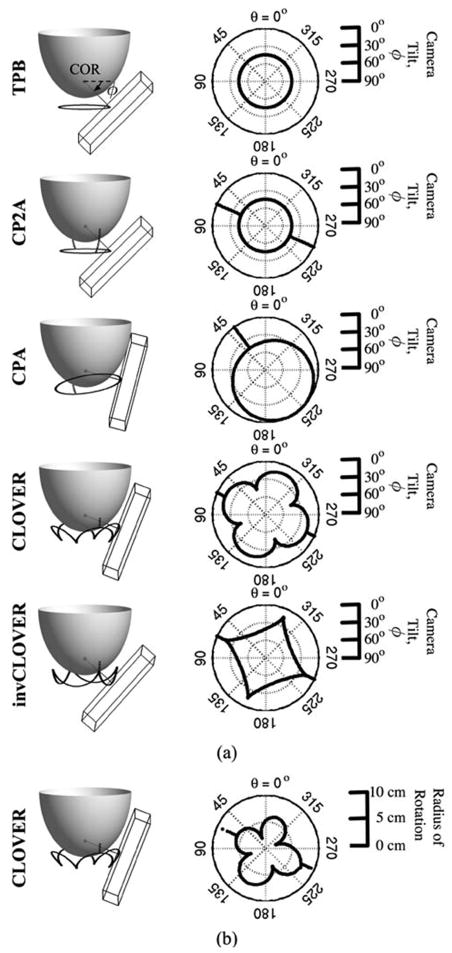
Fig. 7.
(a) Scale schematics of orbits, with 1060 ml breast modeled. The wire-frame box represents the 16 × 20 cm2 active detector FOV, with center on the trajectory (black orbit path) about the breast. Orbits are (Top to Bottom): Tilted-Parallel-Beam (TPB); Circle-Plus-Two-Arcs (CP2A); Circle-Plus-Arc (CPA); Cloverleaf (CLOVER); and Inverse Cloverleaf (invCLOVER) (see, also, Table III). Labeled in TPB schematic are the: center of rotation (COR), located ~2 cm inside the breast along the nipple-chest axis; direction of increased polar camera tilt (small arrow). Dark gray line from COR is perpendicular to the detector face. Note that while these implementations meet Orlov’s criteria for sufficient sampling, simple modifications allow for more viewable breast volume when physical hindrances preclude sufficient sampling. Next to each 3-D schematic are polar plots of camera polar tilt (ϕ) (plotted as a radius, with 90° at center and 0° at edge) versus azimuthal angle (θ) (plotted around the circle from 0° to 360°). (b) For CLOVER orbit, example polar plot of ROR contouring (0 cm radius at center), which allows camera to move close to the breast, as a function of azimuthal angle (θ).

