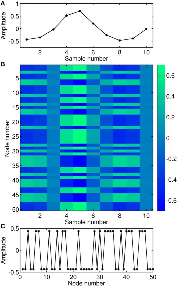
Figure 3.
Illustration of the input encoding. (A) Temporal sequence of the input signal. (B) Matrix representation of the input signal multiplied by the mask, where the virtual nodes act as a pseudo-space. (C) Temporal sequence of the first sample of the input signal multiplied by the mask, i.e., expanded over the corresponding location of the virtual nodes.

