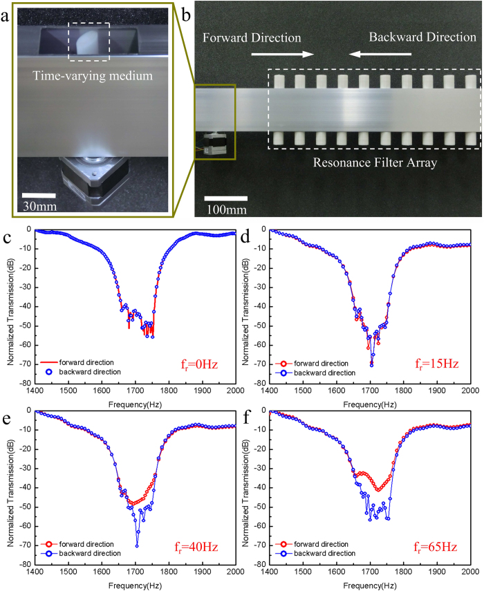
Figure 4. Experimental system and results.
(a) Photography of the time-varying medium installed in an acoustic waveguide with an opening at the top. The time-varying medium is represented by a nylon elliptical-shaped blade driven by a precisely controlled DC motor. (b) Photography of the two-component acoustic wave-guiding system, consisting of a time-varying medium region and a Helmholtz-resonator-array-based acoustic band-stop filter. The definition of forward and backward propagation direction in the experiment is the same as that in the simulation shown in Fig. 2(c–f) Measured normalized power transmission spectra of this system for four different configurations: (c) without the presence of the blade in the system, (d, e & f) rotation frequency fr = 15 Hz, fr = 40 Hz, and fr = 65 Hz respectively. Similar to our numerical investigations, this experimental system experiences a transition from symmetric transmission behavior into asymmetric behavior and consequently an increase in contrast ratio. However, compared with our numerical simulation results, this transition occurs at a higher rotating frequency, because the fabricated filter has a broader bandwidth than the numerically modeled one and a larger rotating frequency is necessary to induce a larger frequency shift so that the high order scattering frequency components can acquire frequencies out of the filter’s stop-band. At the maximum rotation frequency (65 Hz), this device shows a unidirectional transmission property with a contrast ratio up to 20 dB.

