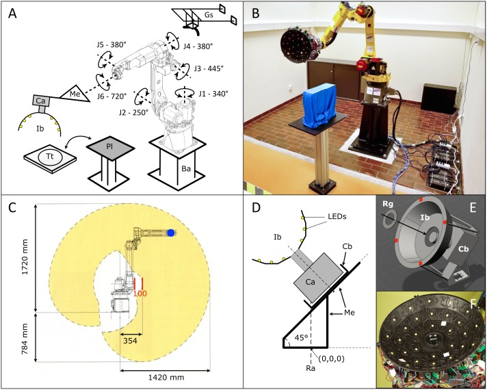
Fig 1. The R2OBBIE scanning system.
A) Schematic representation of the set up; J1–J6, the six axes of the robot; Ba, elevated base; Me, mechanical extension; Ca, camera; Ib, illumination basket; Pl, platform for positioning the target object; Tt, turn-table; Gs, gutter to suspend objects. B) R2OBBIE with the platform configuration. C) The working envelope (yellow) of the robot J5 axis (blue) in the vertical plane passing by J1. D) Schematic view of the camera (Ca) fixed in the camera box (Cb), the illumination basket (Ib), and the mechanical extension; Ra, Rotation axis of J6. E) The illumination basket is fixed to the camera with a ring (Rg) and by four points (red) to the camera box through cylindrical rods. F) Picture of the illumination basket showing the 30 LEDs in place.

