Abstract
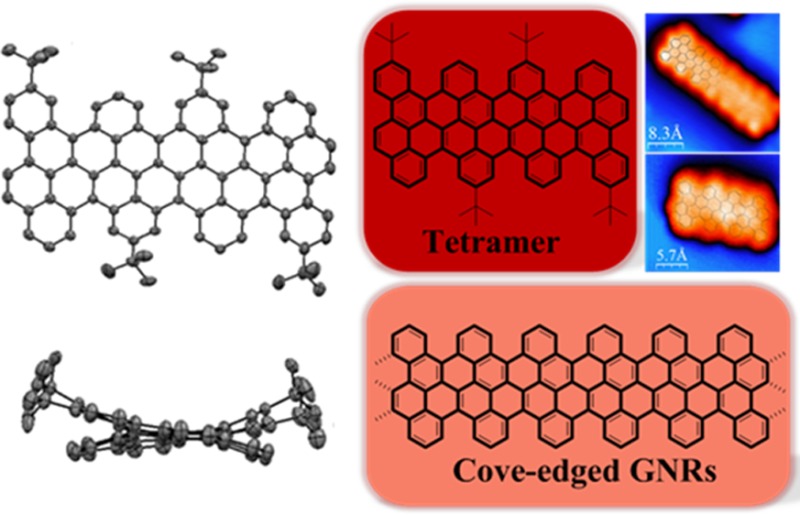
Graphene nanoribbons (GNRs), defined as nanometer-wide strips of graphene, have attracted increasing attention as promising candidates for next-generation semiconductors. Here, we demonstrate a bottom-up strategy toward novel low band gap GNRs (Eg = 1.70 eV) with a well-defined cove-type periphery both in solution and on a solid substrate surface with chrysene as the key monomer. Corresponding cyclized chrysene-based oligomers consisting of the dimer and tetramer are obtained via an Ullmann coupling followed by oxidative intramolecular cyclodehydrogenation in solution, and much higher GNR homologues via on-surface synthesis. These oligomers adopt nonplanar structures due to the steric repulsion between the two C–H bonds at the inner cove position. Characterizations by single crystal X-ray analysis, UV–vis absorption spectroscopy, NMR spectroscopy, and scanning tunneling microscopy (STM) are described. The interpretation is assisted by density functional theory (DFT) calculations.
Introduction
Graphene nanoribbons (GNRs) have been proven to be unique conjugated polymers.1−5 In contrast to graphene, which is semimetallic with zero-band gap, GNRs are tunable band gap semiconductors and thus attractive materials for nanoscale electronic devices, such as field effect transistors.6−9 The width and edge structure of GNRs essentially determine their electronic features such as the band gap and spintronic properties.10−15 One can envisage two different classes of GNRs depending on their periphery structure of the edges (Scheme 1), zigzag-GNRs (ZGNRs) and armchair-GNRs (AGNRs), and these have been extensively investigated both theoretically and experimentally. Two main strategies have been recently established to prepare GNRs, namely “top-down” and “bottom-up” approaches. The “top-down” approach, such as the cutting of graphene, sonochemical extraction from expanded graphite, and unzipping of carbon nanotubes, has produced GNRs with sub-10 nm widths,16−22 revealing their semiconducting nature and excellent charge transport properties. However, “top-down” methods generally suffer from low yields and nonuniform widths, as well as ill-defined edge structures. Moreover, to achieve sufficient band gap control, GNRs should be narrowed to sub-5 nm, at which width scale current lithography methods meet limitations. Thereby, it is highly desirable to produce GNRs with a precise periphery structure and controllable width.
Scheme 1. Edge Structure of Graphene.
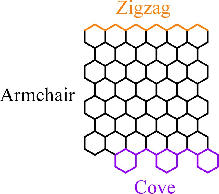
In contrast, “bottom-up” chemical synthesis provides structurally well-defined GNRs with uniform structures.5,23−34 The synthesis is based on solution-mediated or surface-assisted cyclodehydrogenation and “planarization” of three-dimensional polyphenylene precursors. The polyphenylene precursors are designed and synthesized from small organic molecules, providing access to GNRs with different widths and edge structures. Up to now, “bottom-up” synthesis has mainly focused on AGNRs, whereas GNRs with zigzag or cove-type edges (Scheme 1) have remained elusive.35−39
In this study, we demonstrate a novel type of GNR containing a unique cove-type periphery based on 11,11′-dibromo-5,5′-bischrysene (5) as the key monomer (Scheme 2). As model subunits of the infinite cove-edged GNRs, fused chrysene-based oligomers or polycyclic aromatic hydrocarbons (PAHs), namely the dimer 1 (two units of chrysene) and tetramer 2 (four units of chrysene), can be synthesized via the Ullmann coupling reaction of 11,11′-dibromo-5,5′-bischrysene (5b) followed by intramolecularly oxidative cyclodehydrogenation in solution. The structure of the tetramer 2 is unambiguously proven by X-ray single crystal analysis. In comparison with GNRs with armchair or zigzag edges, the cove-edged analogues manifest characteristic nonplanar alternative “up-down” conformations. These PAHs are characterized by UV–vis, matrix-assisted laser desorption/ionization time-of-flight (MALDI-TOF) mass spectrometry (MS), and cyclic voltammetry (CV). The optical band gap of the tetramer is 1.9 eV from the onset of the UV–vis absorption spectrum. We further demonstrate the surface-mediated synthesis of cove-edged GNRs based on monomer 5a, thereby achieving much longer GNRs with lengths up to 20 nm and a width of 0.9 nm. From spectroscopic data and DFT calculations, cove-edged GNRs are shown to possess smaller band gaps than AGNRs of similar width.29
Scheme 2. Structure of Targeted Cove-Edged GNRs.

Results and Discussion
Oligomer Synthesis in Solution
First, the key building block 11,11′-dibromo-5,5′-bischrysene (5) was synthesized as depicted in Scheme 3. Compound 5 was obtained in five steps from 1-bromo-2-iodobenzene (6). 1-Bromo-2-(trimethylsilylethynyl)benzene (7) was prepared by a selective Sonogashira reaction of 6 with trimethylsilylacetylene in excellent yield. Afterward, the bromo group in compound 7 was transformed into the iodo analogue by treatment with 1,2-diiodoethane, affording 1-iodo-2-(trimethylsilylethynyl)benzene 8 in yields of 88–90%. Then, Glaser self-coupling of 8 with CuCl as a catalyst under an ambient atmosphere provided 1,4-bis(o-iodophenyl)-diacetylene (9) in 78–83% yield. Subsequently, the key precursor 1,4-bis(2-(3-bromonaphthalen-2-yl)phenyl)buta-1,3-diyne (11) was furnished through the Suzuki coupling of 9 and 2-bromo-3-naphthaleneboronic acid (10) in 50–56% yield. A final cyclization of compound 11 with PtCl2 as a catalyst under an argon atmosphere at 85 °C for 24 h afforded the desired compound 5 in 70–78% yield.
Scheme 3. Synthetic Route toward the Key Building Block 11,11′-Dibromo-5,5′-bischrysene 5.
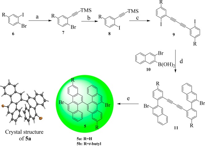
Reagents and conditions: (a) PdCl2(PPh3)2, CuI, Et3N, THF, rt, 24 h, 7a: 82%, 7b: 85%. (b) n-BuLi, THF, ICH2CH2I, −78 °C to rt, 8a: 88%, 8b: 90%. (c) CuCl, DMF, Air, 80 °C, 6 h, 9a: 78%, 9b: 83%. (d) Pd(PPh3)4/Na2CO3, THF/H2O/EtOH, 60 °C, 24h, 11a: 50%, 11b: 56%. (e) PtCl2, Toluene, 85 °C, 24 h, 5a: 70%, 5b: 78%.
Next, the corresponding chrysene oligomers were achieved by Ullmann coupling at 150 °C in dimethyl sulfoxide (DMSO) based on the core building block 5b, as depicted in Scheme 4. Initially, a Yamamoto coupling of compound 5b was attempted at 80 and 100 °C in toluene and dimethylformamide (DMF) solutions, respectively. The reaction failed even under microwave assistance, most likely due to the high steric repulsion between the two C–H bonds at the bay positions of chrysene. Therefore, we turned our attention to the Ullmann coupling at high temperature. Ullmann coupling, when tried at higher temperatures, did not yield the corresponding polymers. Nevertheless, the crude oligomeric mixtures were first separated by silica gel column chromatography, and the pure homologues 12, 13, 14, and 15 were obtained by recycling GPC. Afterward, their cyclodehydrogenation was carried out by using iron(III) chloride (FeCl3) or 2,3-dichloro-5,6-dicyano-1,4-benzoquinone (DDQ)/trifluoromethanesulfonic acid (CF3SO3H) as the Lewis oxidant/acid. The former conditions produced mainly chlorinated products, as confirmed by MALDI-TOF MS (Figure S6). In contrast, cyclodehydrogenation with DDQ and CF3SO3H afforded the desired fused dimer (1) and tetramer (2) successfully. Compounds 1 and 2 were unambiguously characterized by MALDI-TOF MS, as depicted in Figure 1. There is only one dominant peak in the respective mass spectra of 1 and 2, revealing its defined molecular composition; the isotopic distribution pattern of the mass peak is in good agreement with the calculated patterns. Unfortunately, although we could isolate the precursors of hexamer 14 and octamer 15 from the Ullmann-reaction mixtures, only partially fused derivatives of hexamer (3) and octamer (4) were obtained after cyclodehydrogenation, which prevented further purification and separation (Figures S7–S11).
Scheme 4. Synthetic Route toward the Oligomers and Fused Dimer 1 and Tetramer 2.
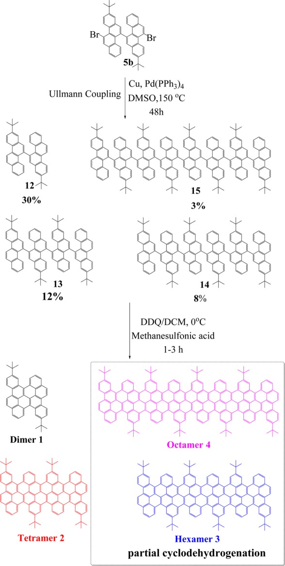
Figure 1.
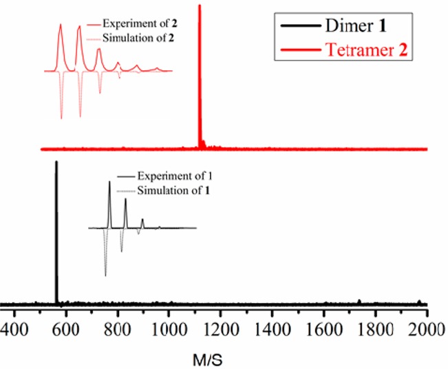
MALDI-TOF MS of 1 and 2.
Structure Analysis of 2
Single crystals of 2 were grown by slow evaporation from a carbon disulfide solution. Compound 2 is a ribbon-shaped molecule with a length and width of 1.8 and 0.9 nm, respectively (Figure 2), and thus serves as a molecular model of its corresponding cove-edged GNRs. Different from the reported graphene molecules with zigzag or armchair peripheries that mostly have planar structures, the outstanding feature of 2 is its nonplanar π-conjugated carbon skeleton, which results from the steric hindrance of its cove periphery. Notably, the benzenoid rings in the cove region in 2 adopt an alternating “up-down” conformation with a mean torsional angle of 38.2°, which suggests that the cove-edged GNRs could also adopt a similar alternating “up-down’ conformation at the periphery.
Figure 2.
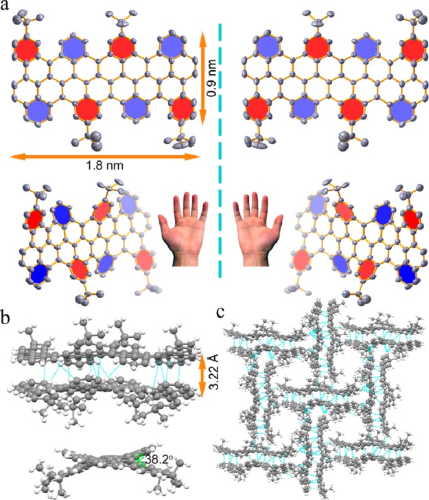
Crystal structure of 2. (a) Top view of enantiomer pair of 2. (b) Crystal packing of dimer from side view. (c) Crystal packing of face-to-face (π–π) and face-to-edge (CH−π).
The distorted carbon framework makes 2 chiral, as shown in Figure 2a. Remarkably, one enantiomer forms a dimer by intermolecular π–π interactions with an interlayer distance as short as 3.22 Å (Figure 2b), whereas such a dimer assembles with its corresponding enantiomeric isomer by face-to-edge CH−π interactions (Figure 2c). Further attempts to separate the enantiomer pair of 2 in solution by chiral HPLC were unfortunately not successful. This is most likely due to the low activation barrier of racemization, as suggested by DFT calculations (vide infra).
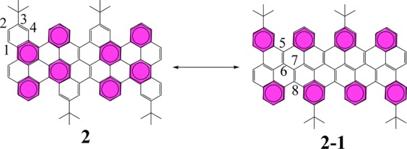
The X-ray diffraction data also disclose the detailed bond parameters of 2 (Figure 3). The C–C bonds at the cove region are obviously longer (1.46 Å), most likely due to the repulsive forces of congested hydrogen atoms. In 2, the chrysene units connect with each other by a single C–C bond, and the distribution of the bond lengths in the chrysene unit is consistent with the resonance structure shown in Scheme 5. The short bond lengths of C(1)–C(2) and C(3)–C(4) support resonance structure 2, whereas the short bond lengths of C(5)–C(6) and C(7)–C(8) imply structure 2-1. Compound 2 thus adopts a π-bond localized resonance structure in the solid state, which is different from that prevailing in fully benzenoid PAHs. Moreover, the bonding–antibonding pattern calculated at the DFT level for the HOMO (HOCO) of the oligomers (ribbons) strongly supports 2-1 as the dominant Clar formula (Figure S12).
Figure 3.
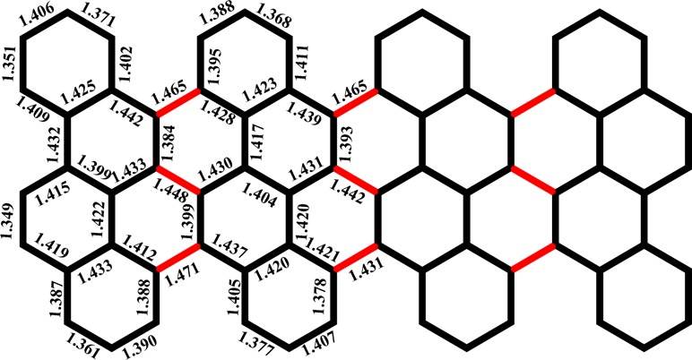
Bond lengths of 2.
Scheme 5. Resonance Structure of 2: Clar Formula Is Represented by Two Resonance Structures Comprising Eight Aromatic Sextets.
Optical and Electrochemical Properties
The UV–vis absorption spectra of precursors 12 and 13, as well as the cyclodehydrogenation compounds 1 and 2 in THF solution, are compared in Figure 4a. This is possible for the fused 1 and 2 because they have sufficient solubility in common organic solvents such as THF, toluene, and trichlorobenzene as a result of the nonplanar cove structure at the periphery and the presence of tert-butyl substituents. The main absorption bands of 1 and 2 are significantly red-shifted compared to those of precursors 12 and 13. Notably, compounds 1 and 2 exhibit similarly shaped UV–vis absorption patterns, including one major band between 300 and 400 nm and another major band peaking at 502 nm with two shoulder peaks at 469 and 439 nm for 1. Compound 2 shows a significant absorption maximum bathochromically shifted by 121 nm relative to that of 1, with an absorption maximum at 623 nm and two other shoulder peaks at 574 and 532 nm, respectively. The optical band gaps of 1 and 2 are determined from the onsets of their UV–vis absorption spectra, which are 2.36 and 1.90 eV, respectively. This result suggests that the energy gap drastically decreases upon increasing the conjugation length of this type of cove ribbon-shaped molecule. Interestingly, cove-edged tetramer 2 features a similarly low band gap (1.90 eV) compared to our previous bottom-up synthesized AGNRs (approximately 1.88 eV) of comparable width but greatly extended length (>100 nm).29 The emission spectra of precursors 12, 13 and fused 1, 2 are shown in Figure 4b. These compounds show fluorescence in THF solution with maxima at 416 and 459 nm for 12 and 13 and 546 and 638 nm for 1 and 2, respectively. The electrochemical properties of 1 and 2 were investigated by means of cyclic voltammetry (CV) in THF solution (Figure S4). According to the CV analysis, compounds 1 and 2 show two reversible oxidations and one irreversible reduction. The HOMO energy levels are estimated from the onsets of the reversible oxidation peaks to be −5.12 and −4.98 eV for 1 and 2, respectively. Thus, the LUMO energy levels are estimated from the optical gaps determined from the onsets of the absorption spectra, and the extracted values are listed in Table 1. These results are fully consistent with the DFT calculations (see below).
Figure 4.
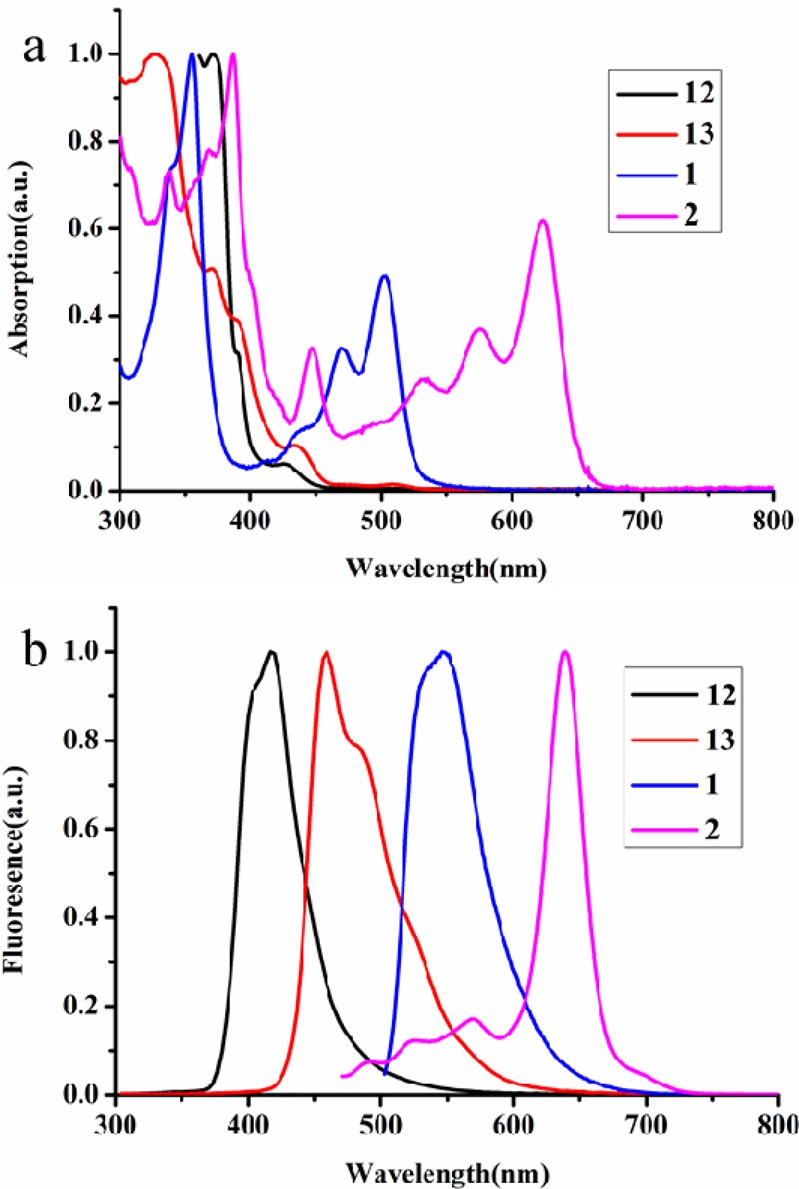
(a) UV–vis absorption spectra and (b) fluorescence spectra of precursor 12, 13 and fused 1, 2 (for all spectra: 10–5 M in THF).
Table 1. Optical and Electrochemical Property for the 1, 2 and Its Corresponding Cove-Edged GNRs.
| compd | λmax (nm) | λem (nm) | λedge (nm) | HOMO (eV)a | LUMO (eV)a | HOMO (eV)b | LUMO (eV)c | Eg(opt) (eV)d | Eg(cal) (eV)a |
|---|---|---|---|---|---|---|---|---|---|
| 1 | 503 | 546 | 526 | –4.67 | –2.06 | –5.12 | –2.76 | 2.36 | 2.61 |
| 2 | 623 | 638 | 652 | –4.38 | –2.37 | –4.98 | –3.08 | 1.90 | 2.01 |
| GNRs | – | – | – | –4.22 | –2.52 | – | – | – | 1.70 |
Calculations were performed at the B3LYP/6-31G (d,p) level.
HOMO levels were calculated from the measured first oxidation potential of CV.
LUMO levels were calculated from the optical band gap Eg(opt) and the respective HOMO levels.
Optical band gaps were estimated from the wavelength of the absorption peak.
Surface Synthesis
As the solution approach suffers from steric hindrance when trying to achieve high molecular weight precursor polymers of chrysene, we turned our attention to the surface-assisted synthesis employing 5a. The on-surface approach is based on the same two steps as used in solution. Precursor monomers are deposited on a supporting media (in this case the solid Au (111) surface) where they are thermally driven to first form polyphenylene oligomers via dehalogenation and subsequent radical combination and then form GNRs by surface-assisted cyclodehydrogenation. The resulting cove-edge GNRs grown under ultrahigh vacuum conditions are shown in the STM40 images in Figure 5, in which the lengths of the GNRs are up to 20 nm. Deposition of monomer 5a on a clean Au (111) surface held at 160 °C and postannealing of the system at 360 °C yield GNRs with lengths ranging from tetramers to hexadecamers (16 chrysene repeating units). There is, however, a clear tendency for interribbon cross-coupling. This can be rationalized in terms of on-surface diffusion and reaction during the cyclodehydrogenation step. The barriers to cyclodehydrogenation and to dehydrogenation at the edge are close. Edge radicals will thus be formed, which attack the C–H from neighboring ribbons and cross-couple, thus partially hindering the formation of longer ribbons (Figure 5a). When on a surface, oligomers adopt a flat geometry due to the tendency of aromatic structures to maximize van der Waals interactions with the surface, in contrast to the nonplanarity obtained in bulk. The apparent height of the GNRs is approximately 1.7 Å, in good agreement with the values observed for other planar aromatic species on metallic surfaces. Despite their tendency to cross-couple, it is possible to find isolated oligomers such as the ones shown in Figure 5b and c. In both cases, the cove-edged structure is discerned, in good agreement with the superimposed schematic model of the ribbon. The formation of longer GNRs under UHV conditions on metallic surfaces compared to those obtained in solution can be rationalized in terms of monomer confinement. Monomers deposited on a surface are confined to two dimensions, in contrast to in solution-based methods, which increase the probability of monomers finding each other and reacting to form longer oligomers. Additionally, metallic surfaces are known to act as a catalyst, thus increasing the oligomerization yield over that of solution-based methods on Au (111).
Figure 5.
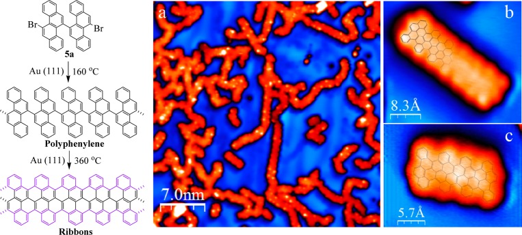
Set of STM images showing cove-edged GNRs grown via on-surface bottom-up reaction of monomer 5a under ultrahigh vacuum conditions. (a) Long range STM image of the oligomers after cyclodehydrogenation. I = 100pA, V = −1.20 V. (b and c) High resolution STM images of two isolated short GNRs with schematic models superimposed. (b) I = 400pA, V = −0.90 V. (c) I = 200 pA, V = −0.70 V.
DFT Calculations
First principle calculations were carried out to obtain further insight into the electronic structure of the oligomers and their corresponding cove-edged GNRs. Geometry optimization was performed at the B3LYP level with the 6-31G (d,p) basis set using the Gaussian09 simulation package. The fused chrysene oligomers adopt a nonplanar conformation, in line with the crystal structural data. Interestingly, multiple conformers that differ by their relative torsion angles along the ribbon (alternating “top-down” or “helical”) and slightly different optical properties are predicted to coexist (Figures S15 and S22). The HOMO and the LUMO orbitals of the most stable conformers are shown in Figure 6, together with their corresponding energies. From these calculations, the band gaps of 1 and 2 are 2.62 and 2.01 eV, respectively. The computed one-electron band gap is reduced upon increasing the ribbon length and is in excellent agreement with experimental results (Table 1). This translates into a red-shifted optical absorption with an extended ribbon length, as predicted from TD-DFT calculations (Figure S14), in line with the observed trends upon going from 1 to 2. The electronic band structure of the corresponding infinite cove-edged GNRs (that features the “up–down” twisted conformation) is presented in Figure S30. The wave functions for the frontier crystal orbitals are reminiscent of those obtained for the oligomers and are fully delocalized across the ribbon width, in contrast to zigzag-GNRs (with localized states at the ribbon edges).41 The bonding–antibonding pattern in the highest occupied crystallic orbital (HOCO) is consistent with formula 2-1 in Scheme 5 being the predominant Clar formula. The electronic band gap of cove-edged GNR infinite ribbon amounts to 1.70 eV. Mobility calculations were also carried out using the Boltzmann transport equation coupled with the deformation potential theory (Table S1), as implemented in the BoltzTrapP software. The mobility is found to be 1.0 × 103 cm2/(V s) for holes and 2.1 × 103 cm2/(V s) for electrons. These results are in line with previous charge transport modeling calculations42 performed at the same level of theory for comparable GNRs, which indicate mobilities on the order 103–104 cm2/(V s) and decreasing as the width of the nanoribbons is reduced.
Figure 6.
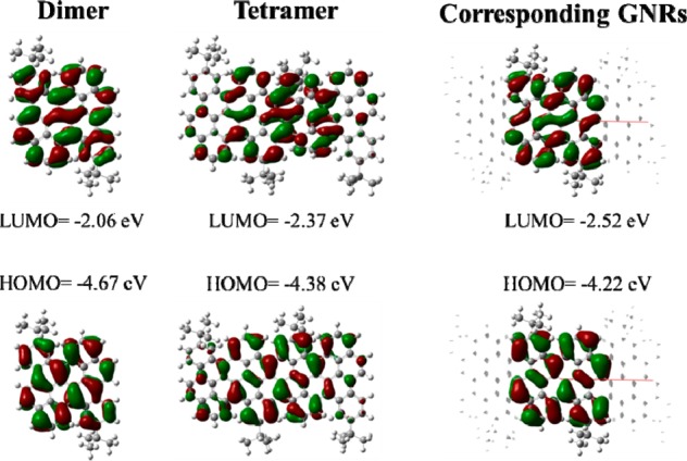
HOMO–LUMO for 1, 2, and the corresponding GNRs.
Conclusion
In summary, we have demonstrated a bottom–up synthetic approach toward unprecedented low band gap GNRs featuring a cove-type periphery. Although the corresponding cyclized chrysene-based oligomers consisting of a dimer and tetramer have been successfully synthesized in solution, the surface-assisted synthesis on a Au (111) surface yields corresponding GNRs with lengths of up to 20 nm. The unambiguous crystallographic characterization of tetramer 2 reveals that the cove-edge structure causes it to deviate from planarity due to steric repulsion and that it possesses an alternative “up–down” geometry. DFT calculations further demonstrate that the “up–down” geometry of the tetramer has lower energy than the “mix” and “helix” conformers. One would safely conclude that the corresponding infinite GNRs also adopt the alternating “up–down” rolling hill. The DFT calculations predict that such cove-edged GNRs possess low band gaps (Eg = 1.70 eV) and high charge carrier mobility for both holes and electrons. Moreover, the electronic properties of the GNRs are expected to be tuned through controlling the width with such cove-type periphery via the bottom–up synthesis. Thereby, the unique optoelectronic properties of such cove-edged GNRs are expected to open a new door toward GNR-based nanoelectronic devices.
Acknowledgments
This work was financially supported by ERCF grants on NANOGRAPH and 2DMATER, DFG Priority Program SPP 1459, EU Project GENIUS, MOLESOL, the EC under Graphene Flagship (No. CNECT-ICT-604391), the Swiss National Science Foundation, and the Office of Naval Research BRC Program. D.B. is a FNRS Research Director.
Supporting Information Available
Experimental details, crystallographic data for 5a, dimer and tetramer, NMR, MALDI-TOF MS, UV–vis spectra, cylic voltammograms, and computational details as well as STM information. The Supporting Information is available free of charge on the ACS Publications website at DOI: 10.1021/jacs.5b03017.
The authors declare no competing financial interest.
Supplementary Material
References
- Son Y. W.; Cohen M. L.; Louie S. G. Nature 2006, 444, 347–349. [DOI] [PubMed] [Google Scholar]
- Li X.; Wang X.; Zhang L.; Lee S.; Dai H. Science 2008, 319, 1229–1232. [DOI] [PubMed] [Google Scholar]
- Jiao L.; Zhang L.; Wang X.; Diankov G.; Dai H. Nature 2009, 458, 877–880. [DOI] [PubMed] [Google Scholar]
- Kosynkin D.; Higginbotham A.; Sinitskii A.; Lomeda J.; Dimiev A.; Price K.; Tour J. Nature 2009, 458, 872–876. [DOI] [PubMed] [Google Scholar]
- Cai J.; Ruffieux P.; Jaafar R.; Bieri M.; Braun T.; Blankenburg S.; Muoth M.; Seitsonen A. P.; Saleh M.; Feng X.; Müllen K.; Fasel R. Nature 2010, 466, 470–473. [DOI] [PubMed] [Google Scholar]
- Neto A. H. C.; Guinea F.; Peres N. M. R.; Novoselov K. S.; Geim A. K. Rev. Mod. Phys. 2009, 81, 109–162. [Google Scholar]
- Gemayel M. E.; Narita A.; Dössel L. F.; Sundaram R. S.; Kiersnowski A.; Pisula W.; Hansen M. R.; Ferrari A. C.; Orgiu E.; Feng X.; Müllen K.; Samori P. Nanoscale 2014, 6, 6301–6314. [DOI] [PubMed] [Google Scholar]
- Bennett P. B.; Pedramrazi Z.; Madani A.; Chen Y. C.; Oteyza D. G.; Chen C.; Fischer F. R.; Crommie M. F.; Bokor J. Appl. Phys. Lett. 2013, 103, 253114. [Google Scholar]
- Wang X.; Ouyang Y.; Li X.; Wang H.; Guo J.; Dai H. Phys. Rew. Lett. 2008, 100, 206803. [DOI] [PubMed] [Google Scholar]
- Ritter K. A.; Lyding J. W. Nat. Mater. 2009, 8, 235–242. [DOI] [PubMed] [Google Scholar]
- Han M.; Özyilmaz B.; Zhang Y.; Kim P. Phys. Rev. Lett. 2007, 98, 206805. [DOI] [PubMed] [Google Scholar]
- Chen Y. C.; Oteyza D. G.; Pedramrazi Z.; Chen C.; Fischer F. R.; Crommie M. F. ACS Nano 2013, 7, 6123–6128. [DOI] [PubMed] [Google Scholar]
- Zhang X.; Yazyev O. V.; Feng J.; Xie L.; Tao C.; Chen Y. C.; Jiao L.; Pedramrazi Z.; Zettl A.; Louie S. G.; Dai H.; Crommie M. F. ACS Nano 2013, 7, 198–202. [DOI] [PubMed] [Google Scholar]
- Tao C.; Jiao L.; Yazyev O. V.; Chen Y. C.; Feng J.; Zhang X.; Capaz R. B.; Tour J. M.; Zettl A.; Louie S. G.; Dai H.; Crommie M. F. Nat. Phys. 2011, 7, 616–620. [Google Scholar]
- Yazyev O. V. Acc. Chem. Res. 2013, 46, 2319–2328. [DOI] [PubMed] [Google Scholar]
- Datta S. S.; Strachan D. R.; Khamis S. M.; Johnson A. T. C. Nano Lett. 2008, 8, 1912–1915. [DOI] [PubMed] [Google Scholar]
- Campos-Delgado J.; Romo-Herrera J.; Jia X.; Cullen D.; Muramatsu H.; Kim Y.; Hayashi T.; Ren Z.; Smith D.; Okuno Y.; Ohba T.; Kanoh H.; Kaneko K.; Endo M.; Terrones H.; Dresselhaus M.; Terrones M. Nano Lett. 2008, 8, 2773–2778. [DOI] [PubMed] [Google Scholar]
- Chen Z. H.; Lin Y. M.; Rooks M. J.; Avouris P. Physica E 2007, 40, 228–232. [Google Scholar]
- Elías A.; Botello-Méndez A.; Meneses-Rodríguez D.; González V.; Ramírez-González D.; Ci L.; Muñoz-Sandoval E.; Ajayan M.; Terrones H.; Terrones M. Nano Lett. 2010, 10, 366–372. [DOI] [PubMed] [Google Scholar]
- Jiao L.; Wang X.; Diankov G.; Wang H.; Dai H. Nat. Nano. 2010, 5, 321–325. [DOI] [PubMed] [Google Scholar]
- Sakaguchi H.; Kawagoe Y.; Hirano Y.; Iruka T.; Yano M.; Nakae T. Adv. Mater. 2014, 26, 4134–4138. [DOI] [PubMed] [Google Scholar]
- Pan Z.; Liu N.; Fu L.; Liu Z. J. Am. Chem. Soc. 2011, 133, 17578–17581. [DOI] [PubMed] [Google Scholar]
- Wu J.; Gherghel L.; Watson M.; Li J.; Wang Z.; Simpson C.; Kolb U.; Müllen K. Macromolecules 2003, 36, 7082–7089. [Google Scholar]
- Yang X.; Dou X.; Rouhanipour A.; Zhi L.; Räder H.; Müllen K. J. Am. Chem. Soc. 2008, 130, 4216–4217. [DOI] [PubMed] [Google Scholar]
- Fogel Y.; Zhi L.; Rouhanipour A.; Andrienko D.; Räder H.; Müllen K. Macromolecules 2009, 42, 6878–6884. [Google Scholar]
- Schwab M. G.; Narita N.; Hernandez Y.; Balandina Y.; Mali K. S.; Feyter S. D.; Feng X.; Müllen K. J. Am. Chem. Soc. 2012, 134, 18169–18172. [DOI] [PubMed] [Google Scholar]
- Dössel L.; Gherghel L.; Feng X.; Müllen K. Angew. Chem., Int. Ed. 2011, 50, 2540–2543. [DOI] [PubMed] [Google Scholar]
- Chen L.; Hernandez Y.; Feng X.; Müllen K. Angew. Chem., Int. Ed. 2012, 51, 7640–7654. [DOI] [PubMed] [Google Scholar]
- Narita A.; Feng X.; Hernandez Y.; Jensen S. A.; Bonn M.; Yang H.; Verzhbitskiy I. A.; Casiraghi C.; Hansen M. R.; Koch A. H. R.; Fytas G.; Ivasenko O.; Li B.; Mali K. S.; Tatyana B.; Mahesh S.; Feyter S. D.; Müllen K. Nat. Chem. 2014, 6, 126–132. [DOI] [PubMed] [Google Scholar]
- Cai J.; Pignedoli C. A.; Talirz L.; Ruffieux P.; Söde H.; Liang L.; Meunier V.; Berger R.; Li R.; Feng X.; Müllen K.; Fasel R. Nat. Nano. 2014, 9, 896–900. [DOI] [PubMed] [Google Scholar]
- Narita A.; Verzhbitskiy I. A.; Frederickx W.; Mali K. S.; Jensen S. N.; Hansen M. R.; Bonn M.; Feyter S. D.; Casiragh C.; Feng X.; Müllen K. ACS Nano 2014, 8, 11622–11630. [DOI] [PubMed] [Google Scholar]
- Plasser F.; Pašalić H.; Gerzabek M. H.; Libisch F.; Reiter R.; Burgdörfer J.; Müller T.; Shepard R.; Lischka H. Angew. Chem., Int. Ed. 2013, 52, 2581–2584. [DOI] [PMC free article] [PubMed] [Google Scholar]
- Vo T. H.; Shekhirev M.; Kunkel D. A.; Morton M. D.; Berglund E.; Kong L.; Wilson P. M.; Dowben P. A.; Enders A.; Sinitskii A. Nat. Commun. 2014, 5, 3189. [DOI] [PubMed] [Google Scholar]
- Chen Y. C.; Cao T.; Chen C.; Pedramrazi Z.; Haberer Z.; Oteyza D. G.; Fischer F. R.; Louie S. G.; Crommie M. F. Nat. Nano. 2015, 10, 156–160. [DOI] [PubMed] [Google Scholar]
- Konishi A.; Hirao Y.; Matsumoto K.; Kurata H.; Kishi R.; Shigeta Y.; Nakano M.; Tokunaga K.; Kamada K.; Kubo T. J. Am. Chem. Soc. 2013, 135, 1430–1437. [DOI] [PubMed] [Google Scholar]
- Konishi A.; Hirao Y.; Nakano M.; Shimizu A.; Botek E.; Champagne B.; Shiomi D.; Sato K.; Takui T.; Matsumoto K.; Kurata H.; Kubo T. J. Am. Chem. Soc. 2010, 132, 11021–11023. [DOI] [PubMed] [Google Scholar]
- Zhong Y.; Kumar B.; Oh S.; Trinh M. T.; Wu Y.; Elbert K.; Li P.; Zhu X.; Xiao S.; Ng F.; Steigerwald M. L.; Nuckolls C. J. Am. Chem. Soc. 2014, 136, 8122–8130. [DOI] [PubMed] [Google Scholar]
- Ball M.; Zhong Y.; Wu Y.; Schenck C.; Ng F.; Steigerwald M.; Xiao S.; Nuckolls C. Acc. Chem. Res. 2015, 48, 267–276. [DOI] [PubMed] [Google Scholar]
- Konishi A.; Hirao Y.; Kurata H.; Kubo T. Solid State Commun. 2013, 175–176, 62–70. [Google Scholar]
- Horcas I.; Fernández R.; Gómez-Rodríguez J. M.; Colchero J.; Gómez-Herrero J.; Baro A. M. Rev. Sci. Instrum. 2007, 78, 013705. [DOI] [PubMed] [Google Scholar]
- Magda G. Z.; Jin X.; Hagymási I.; Vancsó P.; Osváth Z.; Nemes-Incze P.; Hwang C.; Biró L. P.; Tapasztó L. Nature 2014, 514, 608–611. [DOI] [PubMed] [Google Scholar]
- Chen L.; Wang L.; Beljonne D. Carbon 2014, 77, 868–879. [Google Scholar]
Associated Data
This section collects any data citations, data availability statements, or supplementary materials included in this article.


