
Figure 1.
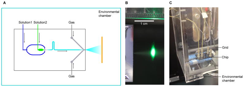
Setup of the time-resolved cryo-EM apparatus. (a) Schematic view of the mixing-spraying device. The EM grid moves perpendicular to the paper. (b) Photograph of the spray of droplets, illuminated by a green laser at the point just before the grid passes through the spray mist in the direction perpendicular to the paper. (c) Photograph of the mixing-spraying chip situated inside the environmental chamber. See also Figure S3.