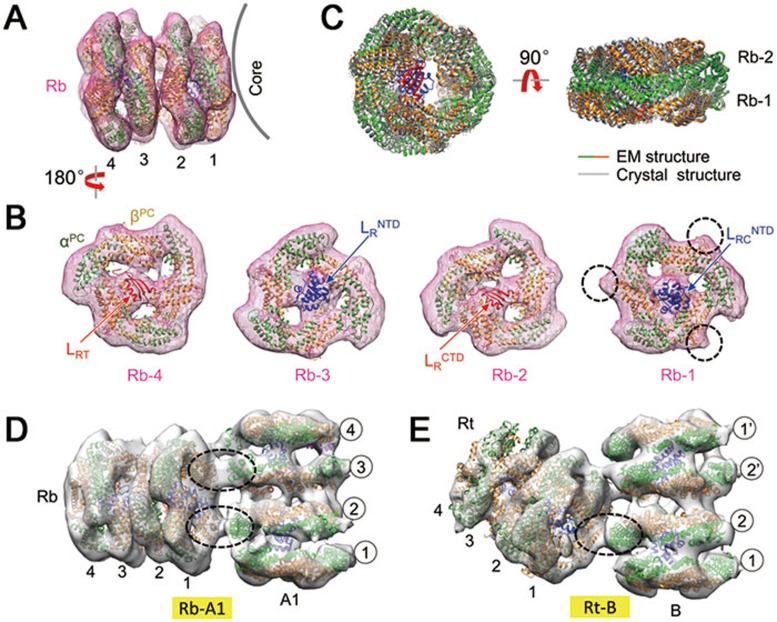
Figure 3.
Assembly of the rods. (A, B) Docking of the bottom rod (Rb). Additional loops in the crystal structure of PC trimers (compared with the APC trimer) are distinguishable in the EM density map and are indicated by dashed circles for Rb-1. (C) Comparison of EM and crystal structures of the PC hexamer. (D, E) Connections between the bottom/top rod (Rb/Rt) and the core cylinder (A1/B). The α-β inter-trimer interactions, which mediate rod-core connections, are circled.

