
Figure 3.
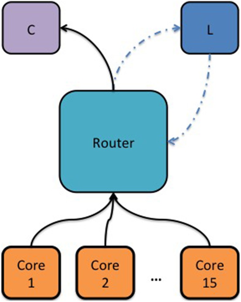
Block diagram showing the topology used to measure the intra-chip packet latency as a function of a congested link and the router's waiting time before dropping a packet. Cores 1–15 were used to generate synthetic MC packets and the router would redirect these packets to a consumer core (C). An additional core was used to measure the MC packet latency (L) by sending a packet to the router periodically and receiving it back. A hardware timer was used to measure the time passed from sending a MC packet to receiving it back.