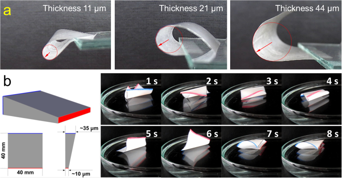
Figure 7.
(a) Photographs of CSE0.3 films (40 × 40 mm2) with thicknesses of 10.9 ± 0.6, 21.2 ± 1.6 and 44.1 ± 3.5 μm in the state of maximal bending. The red arrows are visualizing the corresponding bending radii. (b) CSE0.3 film with a thickness gradient from 10.3 ± 1.1 μm at the one side (marked in red) to 34.7 ± 2.2 μm at the other side (marked in blue). Right panel shows the snapshots of the CSE0.3 film (40 × 40 mm2) coated with CSE3 NPs on water surface at RT (Movie SM6).

