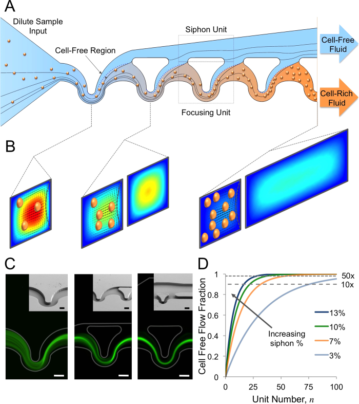
Figure 1. Microfluidic Volume Reduction Using Inertial Focusing and Continuous Siphoning:
(A) Conceptual schematic of inertial focusing siphon sample volume reduction. Starting with a dilute suspension entering the device (i) particles move into the focusing units where the cell free region is formed (ii). By controlling the relative hydraulic resistances of the focusing units (bottom) and the siphon (top) this cell free region is shifted out of the focusing units (iii). The particles still on the focusing unit side form another cell free region in the next focusing unit that is consequently siphoned off (iv). This process is repeated until the desired volume reduction factor is achieved and the siphoned fluid and particle rich fluid leave the device via separate outlets (v). Lines indicate simulated 2D streamlines. (B) Flow simulation cross-sectional plots of the flow in through the inertial focusing siphon device showing the Dean flow vectors and velocity profile which causes the formation of the cell free region within the focusing units and that the overall flow speed decreases as fluid is siphoned off (red-high velocity to blue-low velocity). Particles are superimposed on the flow profiles. (C) A typical sample of fluorescently labeled buffy coat being run through a 10x volume reduction device at three different locations (1st focusing unit, 1st siphoning unit and outlet from left to right respectively) and scanning electron micrographs of the same locations. Scale bars are 50 μm. (D) A plot of the theoretical cell free fraction of the input fluid per unit, or along a device, with different siphon percentages used at each unit increasing from bottom to top (3%, 7%, 10% and 13%).

