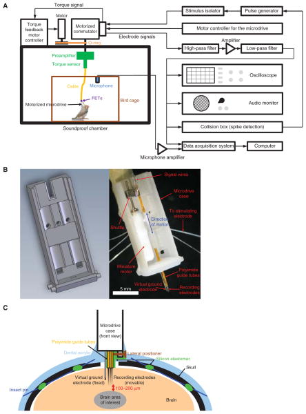
FIGURE 1.
Schematic representation of the electrophysiological recording setup and the microdrive implant. (A) The electrophysiological recording setup. For a photograph of the preamplifier and torque sensor, see Figure 2A. For a photograph of the cable, see Figure 2C. (B) Three-dimensional computer-aided design (CAD) drawing (left) and a photograph (right) of a motorized microdrive. The male Omnetics connector is located on the back. The lateral positioner is omitted for clarity but can be seen in C. Before the implant, the microdrive is protected by covering the open parts with a transparency film. This CAD drawing is available online as a supplementary material (Micro-drive.SLDPRT). (C) Diagram showing the positioning of the microdrive with respect to the skull and the brain. Insect pins go underneath the skull between the two holes in the skull and act as anchors. The lateral positioner provides a way to move the electrodes laterally so that they can enter fresh tissue during each penetration.

