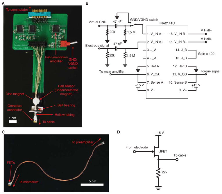
FIGURE 2.
Preamplifier and cable. (A) Photograph of the preamplifier and the torque sensor. Rotation of the cable is detected by a Hall sensor placed underneath the disc magnet. The drawing for this printed circuit board is available online as a supplementary material (PreAmp.brd; PreAmp.sch). (B) Diagram of the preamplifier circuit. For simplicity, only one neural channel is drawn. The 47-nF capacitor and 1.5-MΩ resistor act as a high-pass filter (cutoff frequency 2.3 Hz) before the amplification. A 22-kΩ resistor for the source follower (shown in Fig. 2D) is also included. The GND/VGND switch allows one to select whether GND or VGND is used for the differential amplification. The right half of INA2141U is used for amplifying the torque signal from the Hall sensor. (C) Photograph of the cable. A male Omnetics connector with wires is used at the preamplifier side of the cable. A female Omnetics connector and the surface mount FETs stacked on top of each other are at the microdrive end of the cable. Part numbers are available in the Materials section. The cable is gently braided, and the length of the cable should be such that FETs are 2 cm above the bottom of the cage when the bird is not plugged in (typically 18–20 cm). (D) Schematic of an FET used as a source follower. Each neural channel and the reference ground have their own FET.

