
Fig. 1.
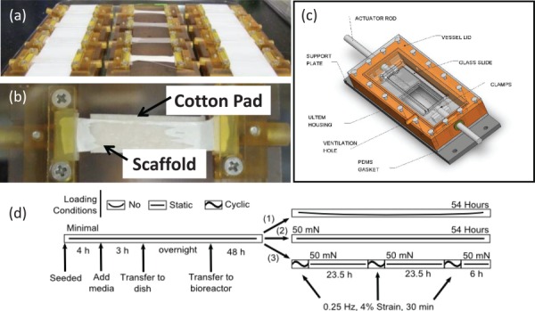
Bioreactor components and operations. (a) Individual mesh between a pair of custom-designed polyetherimide grips and laid over a cotton pad. (b) Troughs to seed multiple meshes and maintain tension. (c) Diagram of the assembled bioreactor [25]. (d) Diagram of the mechanical stimulation time-course. For the no load group (1), meshes were hung slack. For the static load group (2), meshes were strained to 50 mN each day. For the cyclic load group (3), meshes were strained to 50 mN each day and then cyclically strained to an additional 4% at 0.25 Hz for 30 min.