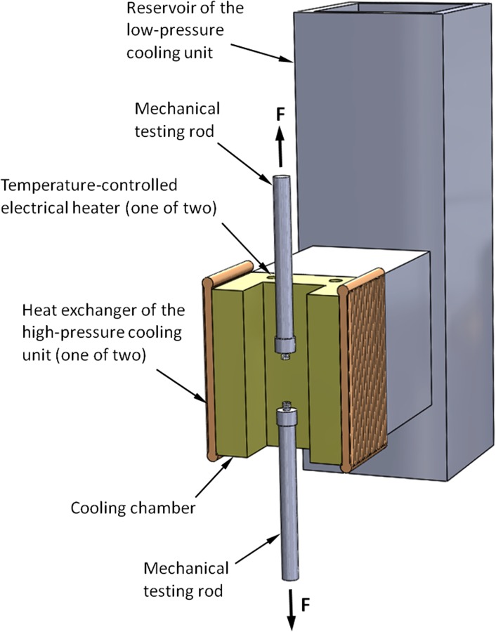
Fig. 1.

Schematic illustration of the key elements of the cooling mechanism for mechanical testing. During experimentation, the artery is attached to the mechanical testing rods (see Fig. 2), the cooling chamber is closed with a brass cover, and the system is covered with thermal insulation from all sides.
