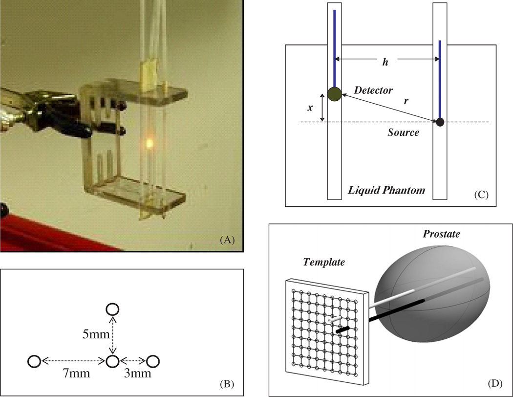
Figure 3.
(A) Picture of the optical property device consisting of 4 parallel catheters positioned at 3 different distances (3, 5 and 7 mm) from the central catheter. The light source is placed in the centre catheter, while the detector is moved along each catheter, positioned at different distances from the light source. (B) Top view of the optical property device pictured in (A). (C) Schematics of the light source and detector placement. The distance between the light source and the detector is h. The light source is placed at a distance x from the surface of the phantom, while the detector is moved along the catheter. The distance from the centre of the detector to the point source is given by . (D) Diagram of cathteter positioning during prostate PDT. The cathteters are placed at fixed distatnces (h) through a template and into the prostate. The light source is placed in one of the cathteters and the isotropic detector is placed in the other catheter.

