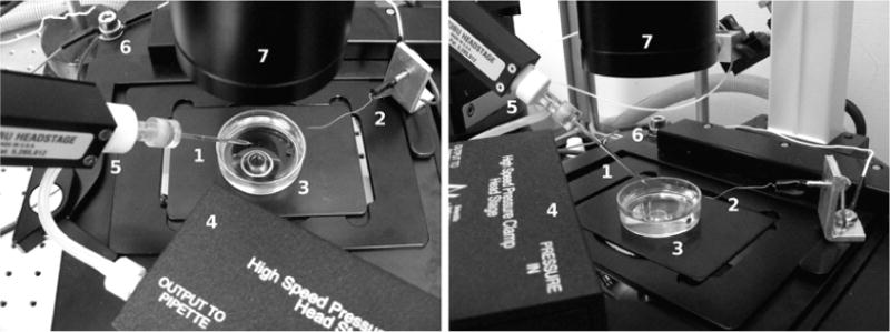
Fig. 4.

Experimental setup, shown from two angles. The glass patch pipette (1) is located above the ground electrode (2) immersed into a petri dish filled with bath buffer (3). The microscope objective is located underneath. Also shown are the pressure-clamp headstage (4), the pipette holder (5), the common ground point (6), and the inverted microscope condenser (7)
