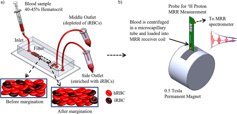
Figure 1. Schematic diagrams.

(a) Schematic diagram of the margination device. The microfluidic separation device that has one inlet, two outlets, and a margination channel of 50 μm in width and 20 mm in length. The insets show the schematic of the cross-sectional view of hRBCs and iRBCs distribution before and after passing through the margination channel. The initially randomly distributed stiffer iRBCs are marginated towards the sidewall, while the more deformable hRBCs migrate towards the axial center of the microchannel. (b) Schematic diagram of the bench top MRR system for R2 measurement. The blood sample is centrifuged in a microcapillary tube and loaded into MRR receiver coil placed inside a 0.5 T permanent magnet. The receiver coil is connected to a bench-top spectrometer for MRR measurements.
