
Figure 2. Channel Design.
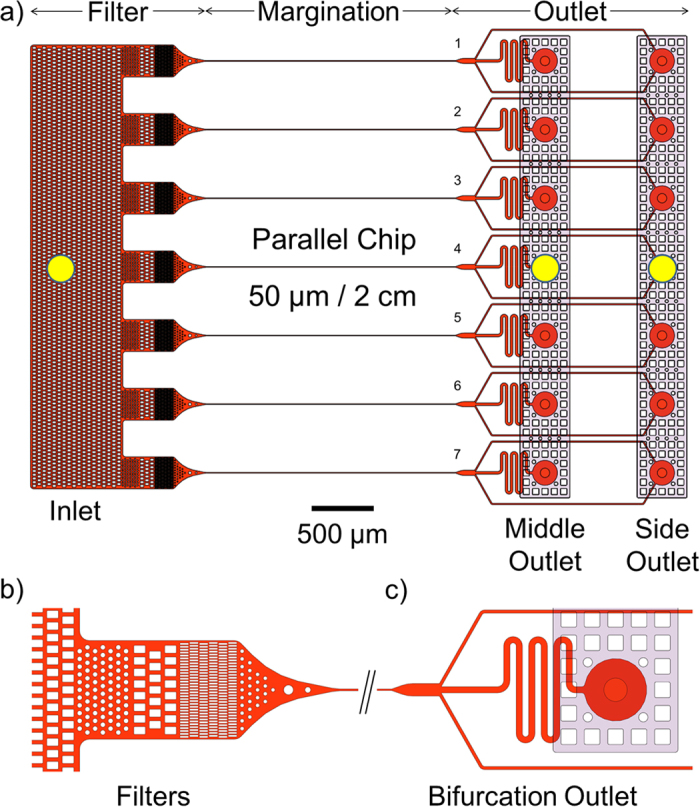
(a) The margination channel design. The microfluidic margination device comprises of two microfluidics components: a margination layer and a cover layer. The margination layer consists of seven parallel margination channels, each with a width of 50 μm, a thickness of 10 μm, and a length of 2 cm. The yellow circles indicate the tubing ports’ location for the inlet, middle, and side outlets of the margination device. (b) Zoom in of the inlet and filtration unit. The microstructures and pillars effectively trap the coagulated blood and large debris to avoid channel blockage in the long and narrow margination channels. (c) Bifurcation outlet at the end of each margination channel. The hRBCs migrates to the axial axis of the microchannel and exit via the middle outlet, while the stiffer iRBCs are marginated to the sidewalls and exit via the side outlets.