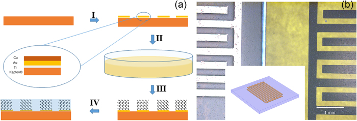
Figure 1.

a) Illustration of the fabrication process. I, photolithography process; II, GO reduction; III, washing and cleaning; IV, electrolyte infiltration. The inset represents the cross-section sketch of the metal interdigit. (b) Optical images of the device before (left) and after (right) rGO assembling and air-drying. Inset: the illustration of the substrate patterned with metal interdigit.
