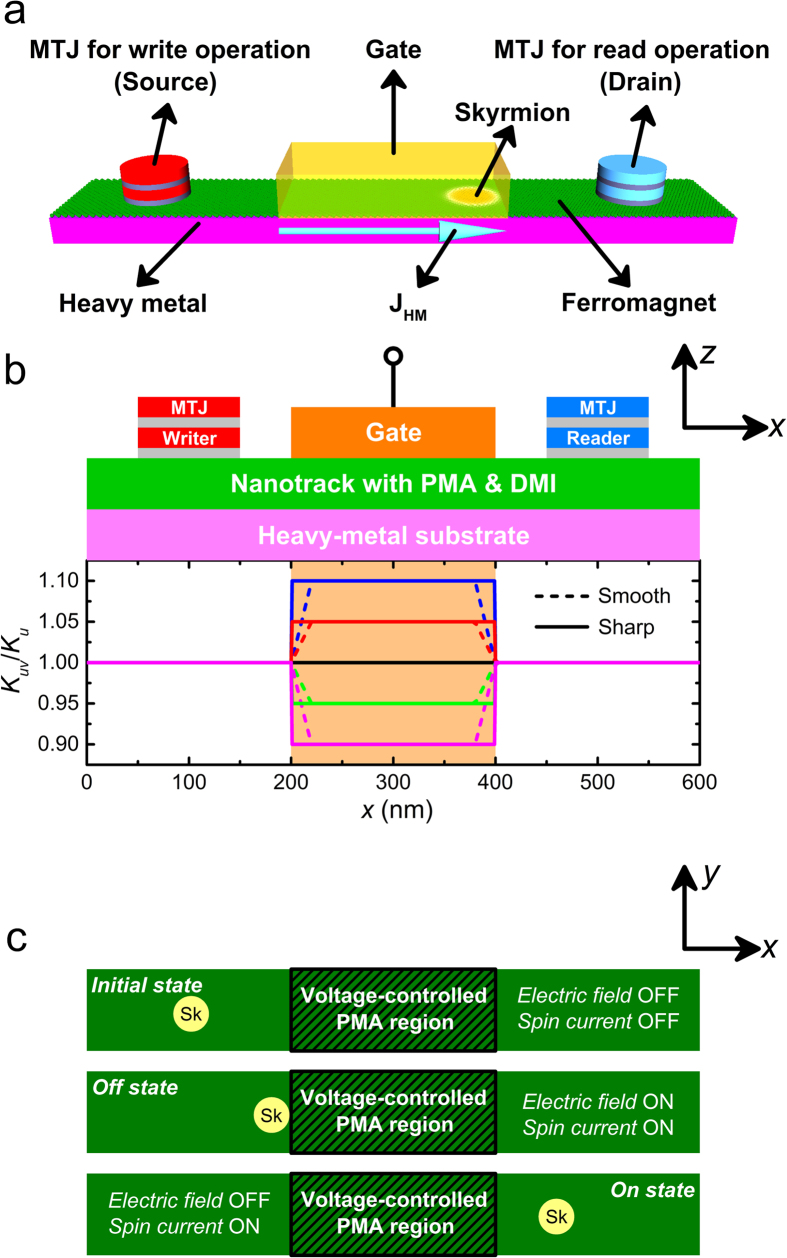
Figure 1.
(a) Design of the skyrmion transistor. The skyrmion is firstly created by the MTJ writer placed at the left side (i.e. the source) and then moves towards the right driven by the spin current, which can be detected when it reaches below the MTJ reader placed at the right side (i.e. the drain). The charge current JHM flows through the heavy metal along the x-direction, which leads to the generation of spin current perpendicularly injected to the ferromagnet due to the spin Hall effect. (b) Schematic view (xz-plane) of the spin-polarized current-driven prototype of the skyrmion transistor. The blue rectangle indicates a nanotrack (length = 600 nm, width = 100 nm and thickness = 1 nm) with perpendicular magnetic anisotropy (PMA) of Ku = 0.8 MJ/m3 and the interface-induced Dzyaloshinskii-Moriya interaction (DMI) of D = 3.5 mJ/m2. The orange rectangle indicates the top electrode for locally changing PMA. The graph presents the variation profile of the PMA of the nanotrack where the PMA of the voltage-gated region Kuv can be tuned. Both smooth and sharp transitions are illustrated in the schematics. (c) Schematic view (xy-plane) of three states of the skyrmion transistor: initial, off and on. Initial state: both the electric field and spin current are turned off; the skyrmion keeps its position on the left side of the nanotrack. Off state: both the electric field and spin current are turned on. The spin current drives the skyrmion moving towards the right, while the electric field, which results in the change of PMA in the voltage-gated region, leads to the termination of the skyrmion when it approaches the voltage-gated region. On state: the electric field is turned off but the spin current is turned on. The skyrmion driven by the spin current passes the voltage-gated region and reaches the right side of the nanotrack.

