Abstract
Here we demonstrate a new imaging system that addresses several major problems limiting the clinical utility of conventional adaptive optics scanning light ophthalmoscopy (AOSLO), including its small field of view (FOV), reliance on patient fixation for targeting imaging, and substantial post-processing time. We previously showed an efficient image based eye tracking method for real-time optical stabilization and image registration in AOSLO. However, in patients with poor fixation, eye motion causes the FOV to drift substantially, causing this approach to fail. We solve that problem here by tracking eye motion at multiple spatial scales simultaneously by optically and electronically integrating a wide FOV SLO (WFSLO) with an AOSLO. This multi-scale approach, implemented with fast tip/tilt mirrors, has a large stabilization range of ± 5.6°. Our method consists of three stages implemented in parallel: 1) coarse optical stabilization driven by a WFSLO image, 2) fine optical stabilization driven by an AOSLO image, and 3) sub-pixel digital registration of the AOSLO image. We evaluated system performance in normal eyes and diseased eyes with poor fixation. Residual image motion with incremental compensation after each stage was: 1) ~2–3 arc minutes, (arcmin) 2) ~0.5–0.8 arcmin and, 3) ~0.05–0.07 arcmin, for normal eyes. Performance in eyes with poor fixation was: 1) ~3–5 arcmin, 2) ~0.7–1.1 arcmin and 3) ~0.07–0.14 arcmin. We demonstrate that this system is capable of reducing image motion by a factor of ~400, on average. This new optical design provides additional benefits for clinical imaging, including a steering subsystem for AOSLO that can be guided by the WFSLO to target specific regions of interest such as retinal pathology and real-time averaging of registered images to eliminate image post-processing.
OCIS codes: (110.1080) Active or adaptive optics, (120.3890) Medical optics instrumentation, (170.3880) Medical and biological imaging, (170.4470) Ophthalmology, (330.2210) Vision - eye movements
1. Introduction
Retinal imaging systems with adaptive optics (AO) are in now in widespread laboratory use among clinical and basic science researchers [1–13]. Adaptive optics scanning light ophthalmoscopy (AOSLO) [14] offers promise as a sensitive diagnostic tool to speed drug discovery for blinding retinal diseases such as age-related macular degeneration (AMD). However, the exquisite spatial resolution of AOSLO compared to traditional wide field of view (FOV) en face clinical imaging systems such as conventional SLO or color fundus photography comes at the cost of a very small FOV. The small FOV of AOSLO causes several major problems that limit its clinical relevance and contribute to it remaining primarily a laboratory tool. The FOV is limited by the human eye’s isoplanatic angle in an AOSLO system and the physical limits of its scanning mirrors and relay optics. The typical FOV of AOSLOs designed for human use is ~1–2°. Most AOSLO systems permit some variability in FOV, with larger FOVs usually coming at the cost of reduced resolution or increased complexity of the optical system.
A small FOV requires numerous locations to be imaged before a clinically meaningful retinal area can be examined (most clinical instruments have a ~30° × 30° or larger FOV). This is usually guided by patient fixation, a cumbersome, time consuming and error-prone process that can be exhausting or frustrating for the patient. A second related problem is that targeting specific retinal areas is difficult. Orienting and image targeting is accomplished by locating retinal landmarks on wide field images obtained with different imaging systems at different time points. This is a process fraught with error, particularly in diseased eyes, since orienting landmarks such as retinal vasculature can be ambiguous and/or appear differently in AOSLO than in the images used for navigation. Targeting can be improved by tightly coupling the fixation targeting system to the navigation images with software [12]; however, the other issues of fatigue, accuracy and long imaging time remain. Finally, even if fixation is accurate, eye movements cause the image to move continuously. Moreover, fixational eye movements tend to be abnormal in patients with retinal disease and poor vision, causing the eye to drift across retinal areas much larger than the AOSLO FOV.
We recently provided an overview of the evolution of real-time SLO and AOSLO eye tracking for image stabilization and demonstrated the performance of an image-based closed-loop optical stabilization and digital image registration method for AOSLO [15]. In this implementation we showed that a two-axis tip/tilt mirror (TTM) could track eye motion with amplitudes of up to ~ ± 3°. We demonstrated that this system was capable of excellent performance in humans with normal fixation. However, the small deflection angle and small FOV made this system unsuitable for patients with poor fixation. Stabilization failed when the eye moved beyond the tracking range of the TTM. This was due to insufficient data overlap between the reference image and the new image because the amplitude of eye motion caused the new image to move out of the reference image FOV (this is occasionally referred to as a ‘frame-out’ error). This system also had difficulty when attempting to quickly re-lock stabilization after a blink or micro-saccade.
To address these problems, we have optically and electronically integrated an AOSLO with a wide-FOV SLO (WFSLO). This permits real-time image stabilization at multiple spatial scales by simultaneously combining optical stabilization driven by the WFSLO and AOSLO images with additional digital registration of the AOSLO image. This implementation was inspired by the work of our colleagues in the Burns laboratory at Indiana University and Physical Sciences Inc. who developed a closed-loop optical eye tracking system for an AOSLO with an integrated wide FOV line scan imaging system [16–18]. This device achieved impressive tracking accuracy (10-15 μm RMS) on AOSLO from the line scanning ophthalmoscope (LSO) disk tracker without additional motion compensation for AOSLO images, but it required substantial tuning of parameters and settings for each eye to achieve stable tracking and robust re-locking [17]. In our new system, large amplitude motion is compensated for at a coarse resolution using a stabilization signal derived from the WFSLO image. This prevents AOSLO frame-out errors, facilitates fast re-locking after microsaccades and blinks, and facilitates robust fine scale AOSLO image-based optical stabilization. Any remaining residual motion is compensated for with real-time digital image registration at sub-pixel resolution. The stabilization performance of this integrated system is evaluated here for both normal eyes with good fixation and diseased eyes with poor fixation.
2. Methods
2.1 Optical system
The integrated optical system is composed of four sub-systems: 1) an AOSLO, 2) a WFSLO, 3) a wide-field optical steering system for the AOSLO, and 4) an infrared (IR) pupil imaging system. Three Windows (Microsoft Corp., Redmond, WA) based computers were employed to work collaboratively for 1) adaptive optics (i.e. wavefront sensing and correction), 2) AOSLO image acquisition, closed-loop image stabilization, and optical steering of the AOSLO raster, and 3) WFSLO retinal imaging, open-loop AOSLO image stabilization from the WFSLO image, and pupil monitoring.
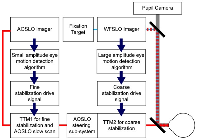
A schematic diagram of the major control blocks of this integrated system is shown in Fig. 1; technical specifications are listed in Table 1.
Fig. 1.
Schematic diagram of the control blocks of the multi-scale stabilization engine. Solid red line denotes AOSLO signal path. Dashed dark red line is WFSLO signal path, thin blue line shows fixation path and thick gray line denotes pupil camera signal path. As can be seen here, WFSLO driven stabilization runs in open loop with the action of TTM2 not being ‘seen’ by the WFSLO system while TTM1 runs in closed loop where the AOSLO image captures the action of both TTMs.
Table 1. Functionality and Specifications of Imaging Sub-systems.
| Subsystem | Functionality | Specifications | Notes |
|---|---|---|---|
| AOSLO | Imaging | Broadband | Fluorescence excitation: 532 nm; Reflectance: 680 & 790 nm |
| Wavefront sensing | Shack-Hartmann WFS | 847 nm illumination; described in [19] | |
| Wavefront correction | Deformable mirror | ALPAO Hi-Speed DM 97; described in [19] | |
| AO control algorithm | Direct slope | Described in [19] | |
| Optical resolution | 2.11 & 2.47 µm | Theoretical; at 680 & 796 nm | |
| FOV | 1.5° × 1.5° | Range: 0.5°–2° | |
| Frame rate | 21 fps | ||
| Stabilization range | ± 2.6° | Linearly scaled from ± 3° TTM deflection angle | |
| Prescription range | –5.5D to + 1.5D | ||
| WFSLO | Imaging | Infrared | 920 nm |
| Optical resolution | ~25 µm | Theoretical; at 920 nm | |
| FOV | ~27° × 23° (H × V) | ~27° × 6.5° during stabilization to increase frame rate (see below) | |
| Frame rate | 15 fps | For largest FOV; ~51 fps with narrow FOV (see above) | |
| Stabilization range | ± 3° | ||
| Prescription range | –10.5D to + 5.5D | ||
| Fixation targets | LEDs (~470 nm) or OLED display | LEDS: (0°, 0°), ( ± 10.3°, ± 10.3°), ( ± 10.3°, 0°) and (0°, ± 10.3°)OLED: 20.6° × 20.6° (0.16°/pixel) | |
| Steering system | Range about fixation | ~ ± 7.5° | For a single fixation target; total range of ~ ± 17.8° across all 9 |
| Pupil camera | Imaging | Infrared | 970 nm LED illumination |
| FOV | 10 × 10 mm | For patient alignment; LEDs switched off during imaging | |
2.2 Optical design
Figure 2 illustrates a flattened diagram of the optical layout of the integrated imaging system. The entire system was assembled on a 4’ × 7.5′ optical table. An all-reflective AOSLO with an adjustable FOV (range: 0.5°–2°; typical: 1.5° × 1.5°) was combined with a refractive point-scan WFSLO with a maximum FOV of 27° × 23°. The all-reflective design for the AOSLO was adopted to limit back reflections and to eliminate chromatic aberration. AOSLO systems commonly use afocal telescopes consisting of pairs of spherical mirrors to relay the pupil planes conjugated to the pupil of the eye [19]. Three pairs of off-axis afocal telescopes were used for the first four pupil conjugates, the final two spherical mirrors were used as the finite conjugate to relay the pupil plane to a two-axis stabilization mirror before the eye. The two large spherical mirrors in the subsystem allowed steering of the AOSLO imaging field across ± 7.5° and improved WFSLO integration. This unique design carries many advantages, including: 1) a large steering range for targeting the AOSLO imaging field, 2) a more compact implementation, 3) a simplified optomechanical layout, and 4) smaller system astigmatism. However, the large steering range introduces some drawbacks, including complexity of system alignment/calibration, field distortion and AOSLO raster rotation; these are discussed in detail below. In order to reduce astigmatism (the dominant aberration degrading image quality), we utilized a 3D folding design, after Dubra and colleagues [19]. The AOSLO was designed for diffraction-limited performance across the entire ± 7.5° steering range at the shortest wavelength used for reflectance imaging (680 nm).
Fig. 2.
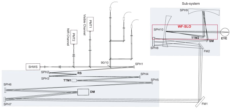
Simplified schematic diagram of the flattened layout of the integrated dual FOV optical system. Shaded areas represent regions where the optics are folded in 3D. The WFSLO and the AOSLO steering and stabilization sub-system are in a two-layer structure; the optical beams are combined using a joint mirror and a dichroic mirror (not shown here, see Fig. 4). All pupil conjugates are labelled in bold fonts. Abbreviations are as follows: 90/10, beam splitter; DM, deformable mirror; FM, flat mirror; PMT, photo-multiplier tube; RS, resonant scanner; SHWS, Shack-Hartmann wavefront sensor; SM, steering mirror; SPH, spherical mirror; TTM, tip-tilt mirror.
Four different wavelength bands are used in the AOSLO. These beams have an entrance pupil size of 7.35 mm in diameter and are coupled into the imaging system using a beam splitter (90/10). Light from the sources are relayed to a fast scanner (SC-30 14K, Electro-Optical Products Corp., Fresh Meadows, NY) by the first pair of spherical mirrors (SPH1 & SPH2). Light from the fast scanner is then relayed to a 2-axis tip/tilt mirror (TTM1) (S-334.2SL, Physik Instrumente, Karlsruhe, Germany) by the second pair of spherical mirrors (SPH3 & SPH4). TTM1 is used as both the slow AOSLO scanner and the AOLSO driven closed-loop optical stabilization mirror. Details are provided in our recent publication [15]. The light beam is then relayed to a wavefront corrector (DM97-15, ALPAO SAS, Montbonnot-Saint-Martin, France) by the third pair of spherical mirrors (SPH5 & SPH6). The last pair of spherical mirrors (SPH7 & SPH8) and two flat mirrors (FM1 & FM2) relay the light to the steering mirror (SM).
2.3 WFSLO
The wide-field imaging system is used to target the AOSLO raster to specific regions of interest and to measure large amplitude eye motion. To overcome technical limitations seen in previous systems [17], we integrated a refractive scanning light ophthalmoscope (SLO) designed specifically for wide-field, high resolution retinal imaging. This system has an illumination pupil of 1 mm and detection pupil of 3 mm and uses an avalanche photodiode (APD, Hamamatsu C10508) detector. Four refractive optics, including an aspherical lens, are used to provide a high contrast image of retinal features suitable for accurate eye motion measurement, such as the fine retinal vasculature. Three custom dichroic mirrors integrate the pupil camera, fixation targets and AOSLO. The WFSLO is designed to have diffraction limited resolution (~25 µm) for the entire ~27° × 23° FOV. The WFSLO image is used to drive a second, identical, tip/tilt mirror (TTM2) for real-time coarse stabilization of the AOSLO image, preventing frame-out and allowing simultaneous fine level stabilization of the AOSLO.
2.4 Optical steering and WFSLO optical stabilization
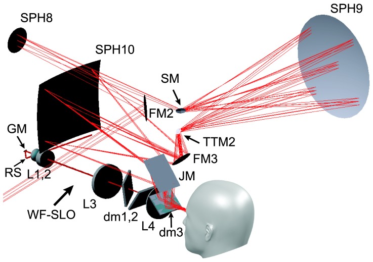
Inspired by the system designed by Burns and colleagues [17], we used a mirror located at a pupil conjugate plane to steer the AOSLO imaging FOV. By mounting a galvo mirror (VM2500 + , Cambridge Technology, Bedford, MA) on top of a rotation stage (360° Travel Micro Mini Stage, Edmund Optics, Barrington, NJ), with the intersection of their rotation axes located exactly at the center of the galvo mirror plane, the raster can be positioned within ± 7.5° . Two large spherical mirrors (400 mm radius of curvature) combined with the steering mirror and TTM2 permits raster beam steering and large amplitude eye motion stabilization. Figure 3 illustrates the complex layout of the steering, large amplitude image stabilization and WFSLO optics. TTM2 receives a motion signal computed from the WFSLO image. The action of TTM2 affects AOSLO image motion only (i.e. the WFSLO cannot ‘see’ the action of TTM2). Therefore, WFSLO stabilization of the AOSLO is in an open-loop control; the implications of this design are discussed in detail later.
Fig. 3.
Detailed view of the complex layout of the steering and WFSLO driven sub-system (upper right shaded portion of Fig. 2). Abbreviations are as follows: dm, dichroic mirror; FM, flat mirror; GM, galvo mirror; JM, joint mirror; L, lens; RS, resonant scanner; SM, steering mirror; SPH, spherical mirror; TTM, tip-tilt mirror.
2.5 Light sources
This complex optical system allows for the delivery of more than five different spectral bands, ranging from 420 to 1050 nm. An 847 nm laser diode is used for wavefront sensing. AOSLO reflectance imaging illumination is provided by two superluminescent diode (SLD) light sources with wavelength bands in the visible (680 nm; 16 nm FWHM) or NIR (790 nm; 40 nm FWHM) (Broadlighter, Superlum, Cork, Ireland). The visible channel can be easily switched to use a 532 nm green laser diode (FiberTec II, Blue Sky Research, Milpitas, CA) for autofluorescence imaging [2,20]. The WFSLO uses an SLD source with a center wavelength of 920 nm and a bandwidth of ~35 nm. The maximum power used for 920 nm SLD illumination is ~520 μW; at this power level the WFSLO raster is usually invisible to the participant. A light safety calculation for the combined retinal irradiance of all light sources was performed with custom software [20]. The typical light levels used (e.g. ~150 µW of 790 nm NIR light and ~15 µW for wavefront sensing at 847 nm) were kept below our internal protocol safety limits which are more conservative than the ANSI maximum permissible exposure [21,22]. For the pupil camera, 970 nm LEDs were used for illumination and only switched on to find the pupil and align the eye to the system prior to imaging.
2.6 WFSLO driven optical stabilization
TTM2 is driven by motion signals calculated from the live WFSLO images using an image-based cross-correlation algorithm similar to the one we described previously for AOSLO [15]. The open-loop control necessitates that this implementation is slightly different than what we described previously for AOSLO; these differences are described in detail below.
The WFSLO resonant scanner runs at 4 kHz. At its maximum FOV of ~27° × 23°, the frame rate is 15 fps. During optical stabilization, the FOV is reduced to ~27° × 6.5° and the live image shows the tracked narrow ‘target’ image superimposed over the wide FOV reference frame; this is illustrated in Fig. 4. The narrow FOV provides three major advantages for eye tracking. First, since the large FOV image is used as the reference image, the probability of matching data increases substantially, reducing the possibility of frame out errors. Second, the pixel sampling density is matched between the target and reference images, allowing the frame rate to increase to ~51 fps. This allows the algorithm to measure eye motion at a higher frequency and substantially increases the control bandwidth. Finally, a further advantage is that the narrow tracking image can be selectively placed at an optimal location within the WFSLO FOV, allowing it to be targeted to areas where the highest contrast features are present. This is particularly important in diseased eyes where large areas of the retina can be low contrast due to disease. This is illustrated in Fig. 4, where the top portion of the WFLSO image from an AMD patient has poor features for cross-correlation while the bottom portion has better features. The target image FOV is switched back to ~27° × 23° when stabilization is manually turned off or if stabilization fails due to a blink, or other reasons. The only disadvantage of the small target image is that the retinal irradiance increases by ~3.5 times (i.e. 23°/6.5°).
Fig. 4.
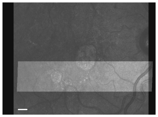
A large FOV image is used as the reference frame for a narrow target image (brighter narrow image in foreground) for WFSLO eye tracking. A narrow target image increases the frame rate to ~51 fps during WFSLO driven optical stabilization. The narrow target image can be placed anywhere in the large reference image FOV, allowing target images to be optimized for cross-correlation by selecting an area with high contrast retinal features. Scale bar is 500μm.
For each target image, the same strip-level approach we described previously for AOSLO is implemented to detect eye motion [15], where each reference image (536 × 448 pixels) and target image (536 × 128 pixels) are divided into multiple strips with 536 × 16 pixels per strip. These images contain only the linear part of the slow scanner motion and crop the nonlinear and retrace portions. Slightly different from our AOSLO implementation, each WFSLO image strip consists of 16 interleaved lines (8 each of the forward and backward scan directions). Strip acquisition time is ~2 milliseconds; hence TTM2 is updated at a rate of ~500 Hz. However, the total latency from the moment the eye motion is detected to the moment TTM2 moves to compensate for that eye motion is ~5–6 milliseconds during fixational drift and longer for a microsaccade, when algorithmic latency, mechanical latency of TTM2, and additional electronic latencies are considered.
The human eye is relatively insensitive to the 920 nm wavelength used for WFSLO imaging, which is advantageous for our purposes where the WFSLO FOV size is frequently updated; most participants could not see the raster. Since the WFSLO scans a larger FOV of the retina but with coarser spatial resolution, TTM2 is naturally used to compensate for large amplitude eye motion at a coarse resolution. The AOSLO only detects the residual image motion left after optical stabilization by TTM2 thus TTM1 is used to stabilize this residual motion at a fine resolution.
In diseased eyes with poor fixation, the eye frequently drifts out of the ± 3° boundary of TTM2. Under this situation, TTM2 is saturated and the stabilization algorithm automatically offloads the additional motion to TTM1. The combination of TTM2 and TTM1 gives a total deflection angle of ~ ± 5.6°, which is sufficient to compensate for the majority of large amplitude fixational drift seen in diseased eyes.
2.7 AOSLO driven optical stabilization, digital registration and image averaging
Closed-loop AOSLO optical stabilization and digital image registration is implemented as we previously reported [15]. As we showed, real-time digital registration after optical stabilization reduces residual image motion to the point where only sub-pixel motion remains, permitting real-time averaging. Here we implement real-time averaging by adding additional steps to ensure that the averaged images are free from motion artifacts that may be introduced by errors in motion detection. The step of image averaging averages the optically stabilized and digitally registered images (referred to simply as ‘stabilized images’ below). Due to unsuccessful cross-correlation for motion detection, the stabilized images are not completely free from motion artifacts. Figure 5 illustrates an example where motion artifacts (Fig. 5(a)) appear in a stabilized image (Fig. 5(c)) because of incorrect results from cross-correlation with the reference image (Fig. 5(b)). These incorrect results come from poor local image quality or other reasons beyond the capability of translational cross-correlation, e.g., torsion. These local areas with motion artifacts must be cropped out (Fig. 5(d)) before averaging or they will introduce blur into the averaged image.
Fig. 5.
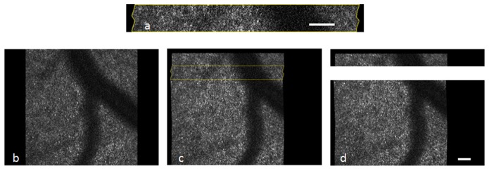
Motion artifacts (a) appear in some stabilized images due to unsuccessful cross-correlation between the reference (b) and target (c) images. Yellow outline in (c) denotes area shown in (a). After a second round of cross-correlation, motion artifacts are cropped out, and the final image (d) is used for real-time averaging. Scale bars are 50 µm.
If we define the cross-correlation for optical stabilization and digital registration as the ‘first round’ of cross-correlation which detects eye motion between the reference image and a target image, here we implement a ‘second round’ of cross-correlation between the reference image and a stabilized image. After the first round of cross-correlation, if the target image has been stabilized successfully, the relationship between the reference image and the stabilized target image (e.g. Fig. 5(c)) must meet the following two reasonable criteria at any location of the image: 1) the amount of motion is sub pixel, and 2) the correlation coefficient is reasonably high (e.g. ≥0.7) as image features between the reference and stabilized target have nearly complete overlap with only a sub-pixel offset. When either criterion fails, we can conclude that this individual strip is not stabilized successfully from the first round of cross-correlation, and it should be excluded from the step of image averaging. The thresholds for these constraints can be adjusted depending upon individual subjects and/or individual imaging systems. For example, when the subject has poor-fixation and/or images are low-contrast, the threshold for motion should be increased to tolerate more pixels and the threshold for the correlation coefficient should be appropriately decreased to keep more strips.
Due to the fact that the amount of motion is in sub pixels from any strip pair between the reference image and the stabilized target image, strip size for the second round of cross-correlation can be small as long as they contain sufficient data (and image features) for cross-correlation to exclude ambiguity. Potentially, the size of a strip can be reduced to a single line. A small strip size has two advantages: 1) it reduces computational cost, and 2) it discards only motion artifacts and keeps as much useful data as possible for image averaging. Figure 5(d) illustrates the result of the processed stabilized image after the second round of cross-correlation where the motion artifacts have been filtered out. The filtered image is then used for averaging
The second round of cross-correlation can be run offline or in real-time. To filter out motion artifacts in real-time, it can be implemented in either of two different approaches: A) at the end of the current frame during the retrace period of the slow scanner where the retracing time is adjustable based on the computation time of cross-correlation, or B) right after the detection of strip motion from the first round of cross-correlation that is used to drive TTM1. In approach B, it is required that the algorithm finishes all computation before the next strip is received. Also in approach B, the first round of cross-correlation calculates motion of the most recent strip, and the second round of cross-correlation processes the stabilized image from the previous frame.
2.8 Real-time control of stabilization and steering for data acquisition across large areas
The goal of integrating stabilization and steering is to improve imaging efficiency by eliminating most, if not all, post processing. In our existing implementation, stabilization and steering work together to accomplish this, as illustrated in Fig. 6.
Fig. 6.
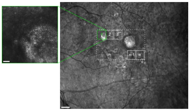
Integrated steering and stabilization allows a target area (dashed rectangle) in the WFSLO image (right) to be imaged with AOSLO (left) with minimal overlap between adjacent fields (e.g. areas as 1, 2, 3). Scale bar for AOSLO is 50 um and scale bar for WFSLO image is 500 um.
In the example of Fig. 6, the left image is an AOSLO image which is a ‘zoomed-in’ view of the area denoted by the square labelled ‘1’, outlined in green on the WFSLO image to the right. Each small square labeled ‘1’, ‘2’, ‘3′, …, ‘n’ represents a single AOSLO FOV. AOSLO imaging is targeted to these locations by the steering mirror. A typical imaging goal may be to examine the entire retinal area enclosed by the dotted rectangle in Fig. 6, eventually to achieve a stitched large FOV and high-resolution AOSLO image from each individual retinal location labeled with ‘1’, ‘2’, ‘3′, …, ‘n’. As we describe in the introduction, the common approach uses a moveable fixation target that is repeatedly repositioned to different locations. Without optical stabilization, even careful fixation causes continuous eye motion that moves the targeted retinal area, making it difficult to precisely control the overlap between adjacent imaging locations. This necessitates positioning fixation targets extremely close together to avoid gaps in the data, a highly inefficient approach. With WFSLO optical stabilization, the control of overlap between two adjacent AOSLO imaging locations becomes more predictable, since residual image motion on AOSLO after WFSLO optical compensation (with TTM2) is significantly smaller. A typical procedure to run an imaging session in our system is listed below.
-
1)
Start WFSLO optical stabilization (i.e. activate TTM2)
-
2)
Steer AOSLO imaging field to retinal location k, where k = 1, 2, 3, …, n-1, n…
-
3)
Start AOSLO optical stabilization and digital registration (i.e. activate TTM1)
-
4)
Start AOSLO data recording and simultaneous image averaging
-
5)
After a fixed number of frames or required image quality has been achieved, output an averaged image for this location
-
6)
Turn off AOSLO optical stabilization (i.e. reset TTM1)
-
7)
Repeat steps 2-6 until all n retinal locations are finished
From this procedure it can be seen that it is preferable for WFSLO stabilization to remain on throughout the imaging session so the AOSLO imaging location can be precisely controlled and to minimize overlap between adjacent imaging locations. Minimal overlap increases efficiency, reduces total imaging session duration and minimizes light exposure. The optical implementation allows continuous WFSLO stabilization regardless of the action of TTM1, TTM2, and SM. Ideally, a single WFSLO reference image is used throughout the entire imaging session to ensure that TTM2 tracks the same retinal location; this permits continuous WFSLO stabilization. The WFSLO reference image can be a single frame (e.g. background of Fig. 4) or an averaged high SNR image (e.g. Fig. 6). It is important to include several breaks during an imaging session to minimize patient fatigue and refresh the tear film of the eye; WFSLO stabilization is turned off automatically during breaks, by detecting when the mean pixel value and standard deviation of the live image fall below a defined threshold.
2.9 Evaluation of stabilization performance
Stabilization performance was evaluated at 17 locations that covered the full range of the steering system. These positions consisted of two 3 × 3 grids centered on the fovea, one with imaging locations spaced at ~3° and the other with spacing of ~10°. The central nine locations were reached using a single fixation target, while the additional 8 positions were reached using the 8 other LED fixation targets. All 17 locations were tested for normal eyes; only the central 9 locations were tested for diseased eyes. At each location, we acquired 3–5 10-second videos from the WFSLO and AOSLO, representing the following conditions:
-
1)
No stabilization
-
2)
WFSLO stabilization only
-
3)
WFSLO + AOSLO stabilization
-
4)
WFSLO + AOSLO stabilization + digital registration
2.10 Participants
To demonstrate the performance of the stabilization system, we tested it on 5 participants with normal vision and 5 patients with diseases that caused poor fixation: AMD, cone-rod dystrophy (CRD), Retinitis pigmentosa (RP), choroideremia (CHM), and macular hole (MAC) respectively. The 5 normal participants ranged in age from 23 to 65; the 5 patients ranged in age from 25 to 79. Additionally, prior to evaluating the stabilization performance we evaluated the optical performance alone by imaging an additional 5 normal participants and 2 more patients with AMD. Participants with normal vision were recruited from the University of Rochester and the local community. Patients were recruited from the faculty practice of the Flaum Eye Institute at the University of Rochester Medical Center. All participants gave written informed consent after the nature of the experiments and any possible risks were explained both verbally and in writing. All experiments were approved by the Research Subjects Review Board of the University of Rochester and adhered to the Tenets of the Declaration of Helsinki.
3. Results
3.1 Optical system performance
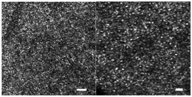
Image analysis in 10 normal participants and 7 patients revealed finite image contrast at spatial frequencies corresponding to 2.2 μm for a 6.6 mm pupil at 680 nm. Figure 7 illustrates images of foveal cones and perifoveal rods and cones (10° eccentricity) imaged in a normal 23 year old woman. Figure 7 (left panel) represents a registered and averaged image from a 0.7° AOSLO imaging field (pixel sampling = 0.334 µm/pixel). These images illustrate that the optical system can resolve almost every single cone photoreceptor in the fovea and rods in perifovea (Fig. 7, right panel). In addition to the high AOSLO image quality, the system also showed high light throughput and sensitivity despite its complicated design. The throughput is ~40% for the entire system; images shown in Fig. 7 were obtained with ~120 μW of 680 nm imaging light.
Fig. 7.
The resolution of the AOSLO was not compromised with the additional features we have added, as we maintained the visibility of not only the foveal cones (left) but also rods in the periphery (right). Scale bars are 20 µm (left) and 10 µm (right).
Due to the nature of finite conjugate design in an off-axis reflective mode, particularly at larger steering angles, the steering performance of the optical system suffers slightly from its non-symmetric design, resulting in some field distortion and raster rotation. We simulated the raster rotation for nine steering locations in a perfect model eye (aberration free and focal length f = 16.8 mm). Figure 8 shows the raster rotation at these steering positions from the simulation which is consistent with empirical results. The distortion of the system is 0.5% at full field. The maximum rotation angle of the scanning raster is ~9.3°.
Fig. 8.
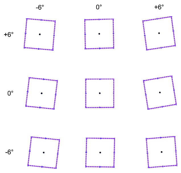
Simulations of the AOSLO raster at the most extreme steering angles demonstrate the field distortion and raster rotation induced by steering. These simulations were in line with empirical results.
3.2 Stabilization performance
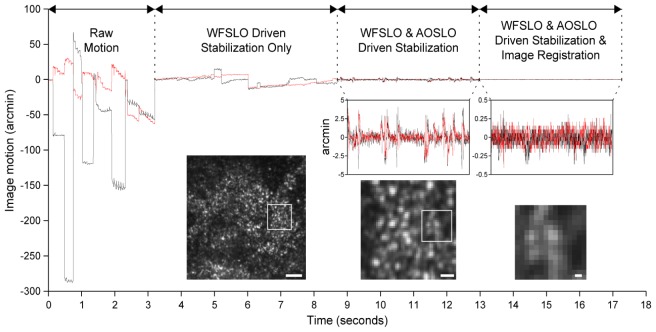
Figure 9 illustrates an example of image motion from an AMD patient. It first shows motion without any stabilization (i.e. raw motion), and then with stabilization, incrementally: A) optical stabilization from WFSLO, B) optical stabilization from both WFSLO and AOSLO, and C) optical stabilization from both WFSLO and AOSLO plus digital registration of the AOSLO image. All three stages of stabilization are usually run simultaneously during imaging, they are only shown here consecutively to illustrate the successive levels of motion compensation obtained at each stage. In this particular case, the motion is reduced by 610 times after all three stages of compensation. An example AOSLO video without any stabilization is illustrated in Media 1 (1.5MB, MPG) , and an AOSLO video with WFSLO driven optical stabilization, but without AOSLO optical stabilization and digital registration, is illustrated in Media 2 (1.1MB, MPG) . Media 3 (966KB, MPG) is a video from the same AMD patient that shows the full implementation of all three stages running simultaneously. The action of WFSLO eye tracking is illustrated in Media 4 (984KB, MPG) .
Fig. 9.
Each stage of motion compensation reduces the amplitude of residual motion. Note that each stage is shown running consecutively here for illustrative purposes but in practice all three stages run simultaneously. White squares in left image and center images denote areas of images shown to the right. Scale bars for the images are (from left to right): 25 µm, 5 µm, and 1 µm.
The averaged stabilization performance for all 10 subjects is illustrated in Fig. 10. These results demonstrate that each successive stage of stabilization reduces the magnitude of retinal image motion. When all three stages of stabilization are activated, image motion is reduced by a factor of ~400, on average. It is important to point out that optical stabilization from the two TTM’s may alter image quality, but we find that the similarity of averaged images between the cases with and without optical stabilization is 0.8842-0.9503 in correlation coefficient from the 10 subjects. The variation in these correlation coefficients is dominantly caused by eye torsion where the videos with and without tracking were recorded at different time from the same retinal location.
Fig. 10.
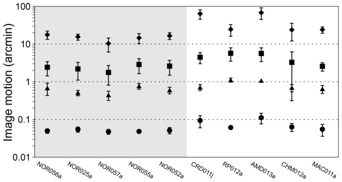
Performance for each successive stage of eye motion compensation. Diamonds: raw motion; squares: WFSLO driven optical stabilization only; triangles: WFSLO & AOSLO driven optical stabilization combined; circles: WFSLO & AOSLO driven optical stabilization combined with digital registration. The error bars denote standard deviation.
3.3 Combining real-time steering and multi-scale stabilization for efficient data acquisition
Figure 11 illustrates an imaging result obtained from an AMD patient (AMD018a), using the imaging protocol described in Section 2.8. It took ~35 minutes to sweep through an 8° × 6° area. This represents a substantial reduction in time compared to the ~8–10 hours it would typically take in our laboratory for an imaging technician to acquire (~1-2 hours) and manually register (~7-8 hours) the same amount of data using a traditional AOSLO system without steering, stabilization and automatic averaging. It should be noted that this does not include the amount of time required to stitch the images together; this would still need to be done manually for each (as it was for the images shown in Fig. 11). The amount of time needed for image stitching would be about the same for each case, but perhaps slightly less for the images acquired with steering that have less overlap than those acquired by fixation targeting. However, there are several advantages of this new instrument for streamlining and automating the stitching process; these are provided in the discussion section below.
Fig. 11.
A stitched 8° × 4° montage (cropped from an imaging area of 8° × 6°) from an AMD patient imaged with the protocol described in section 2.8 (see Fig. 6).
4. Discussion
4.1 Optimization of optical design
This design allowed two unique imaging systems to be integrated together optically and electronically for a substantial gain in functionality. For practical purposes, we integrated existing WFSLO and AOSLO systems by modifying the AOSLO described in [19] by adding additional optical elements to combine it with the WFSLO and add AOSLO steering and stabilization. However, several constraints were imposed due to our need to utilize existing hardware that could be avoided in future system designs where both the wide FOV imaging system and AOSLO are designed from the ground up to be one integrated system.
One of the major issues is related to the finite conjugate design for wide-field positioning and motion stabilization. The nature of the off-axis reflective implementation for wide field steering resulted in increased spherical aberration, and introduced image distortion and raster rotation that increased with steering angle. It would be useful to minimize these problems as much as possible in future designs. In the current implementation, we must perform a detailed system steering position calibration and generate a look-up table for reference. Steering calibration is complicated and highly dependent on system alignment. To solve this problem, we could still use the off-axis finite conjugate design but would have to decrease the steering range to minimize system nonlinearity. An alternative solution is to utilize an infinite conjugate design for the steering functionality. For a small steering field (e.g. <10°), such a design would facilitate better optical performance. This is compared to our current implementation in the diagrams shown in Fig. 12. However, given our constraints here, the improved approach shown in Fig. 12(b) would have made for an even more complicated optical design for the integrated system, so we opted to go with the current approach.
Fig. 12.
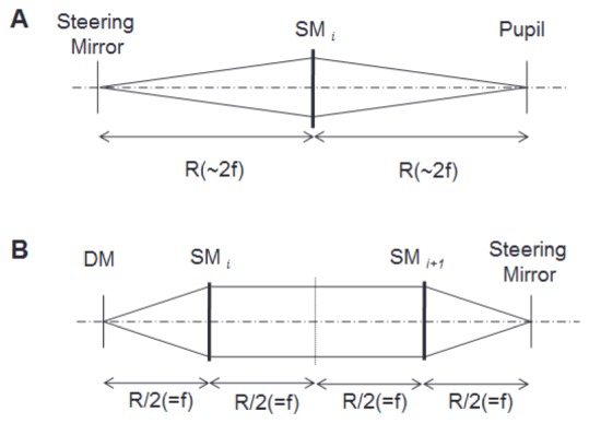
Simplified schematic diagrams for two steering optical solutions: a finite pupil conjugate design (A) and an infinite pupil conjugate design (B).
4.2 Closed-loop or open-loop WFSLO driven stabilization?
One might suggest an alternative design that simplifies the system by using one TTM with a larger deflection angle and sufficient resolution (e.g. a 2-axis galvanometer mirror or two 1-D galvanometer mirrors) to close the loop among WFSLO, AOSLO and the TTM. As mentioned above, for this first generation system, we worked within constraints imposed by combining existing systems and the need to utilize existing equipment. However, the advantages of such an implementation (shown schematically in Fig. 13) are straightforward:
Fig. 13.
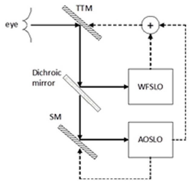
Block diagram of a completely closed-loop multi-scale optical stabilization system. Solid arrows are optical paths and dashed arrows are electronic paths. ( + ) denotes a simple digital or analog signal addition.
More robust image stabilization and fewer optical surfaces. Therefore, it is worthwhile to explore this feature as it presents another major advantage: the potential to optically compensate for microsaccades. In the fully closed-loop system shown schematically in Fig. 13, the TTM becomes the only stabilization mirror and receives motion signals from both the WFSLO and AOSLO that are integrated with simple addition.
In our current open-loop WFSLO design, the algorithm is able to detect eye motion accurately most of the time, but the algorithm will output spurious signals occasionally caused by image noise and/or non-translational image motion. Due to the fact that the open-loop control has zero tolerance against mistakes, the motion detection algorithm must be very conservative to determine whether a larger-than-usual motion is caused by a true microsaccade or a spurious motion from an unsuccessful cross-correlation. Accidentally adding a spurious motion on the WFSLO driven TTM2 will generate undesired jittering of the AOSLO image, which is worse than having no action from TTM2 at all. In our current WFSLO implementation, we consider it to be a ‘true’ micro-saccade if the following two conditions are satisfied: 1) three consecutive strips have larger-than-usual motion (e.g. several to tens of arcmin), and 2) they are all moving in the same direction. If a larger-than-usual motion is followed by a small motion, or is followed by another larger-than-usual motion but in the opposite direction, this larger-than-usual motion will be treated as spurious motion and TTM2 will be frozen at the existing position. Figure 14 illustrates all potential latencies from the open-loop WFSLO when it is trying to correct a microsaccade that occurs at strip 3 but is not compensated for until somewhere in strip 8.
Fig. 14.
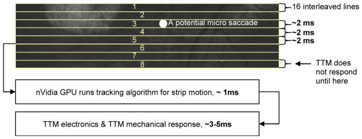
A large latency is involved in the existing open-loop WFSLO driven optical stabilization system when attempting to compensate for a microsaccade.
From Fig. 14 it can be seen that three continuous strips accumulate 6 milliseconds of latency from WFSLO data acquisition, plus 1 millisecond of computational latency, and 3–5 milliseconds of mechanical latency, as a consequence, the total latency is 10–12 milliseconds. This means that TTM2 will not respond to a microsaccade until 10–12 milliseconds after it is detected. This large latency makes it impossible for the TTM to compensate for microsaccades. It is worthwhile to point out that TTM latency increases for larger step sizes. The TTMs we use here have ~2 milliseconds of mechanical latency for small input signals, such as for stabilizing eye drift, but microsaccades have large enough motion (e.g. tens of arcmin) to cause the mechanical latency to increase to 3–5 milliseconds due to the larger step size of the input signal.
The major advantage of a closed-loop WFSLO driven large amplitude motion signal is the ability to measure residual image motion, hence motion detection from the algorithm will be more robust and self-correcting. Further, such a system would have a shorter sampling latency, based on the time of a single strip (~2 milliseconds instead of the current 6 milliseconds). Therefore, future work should examine whether microsaccades can be compensated for with a closed-loop WFSLO stabilization system, preferably with a faster TTM.
4.3 Continuous WFSLO optical stabilization of torsion
We currently implement the approach from Stevenson and Roorda [23] to detect torsion. The main problem that our current approach does not adequately address is reporting correct eye/head torsion (i.e. rotation), when the amount of torsion is larger than the algorithm can detect. It is crucial to find a more robust and fast algorithm for torsion detection. Precise measurement of image rotation is critically important for both WFSLO and AOSLO. For clinical applications, it is desirable to have continuous WFSLO eye tracking, regardless of eye/head torsion and rotations in the image. Moreover, we want to be able to use the WFSLO to keep track of all imaging locations. This will permit efficient data acquisition and limit light exposure to the retina and requires only moderate optical and electronic calibration. This will also facilitate having the ability to repeatedly and precisely target exact retinal locations for clinical studies (e.g. longitudinal studies of disease progression).
4.4 Optimization of scanner orientation between WFSLO and AOSLO
After analyzing all data from both AOSLO and WFSLO, we found that optical stabilization performance was slightly better in the direction of the fast scan. The averaged residual image motion after WFSLO optical stabilization was 5%–15% better in the fast scan direction than in the slow scan direction. This difference can be explained by 1) the fast scan direction has less image distortion than the slow scan direction does, and 2) strip shape, as illustrated in Fig. 14, allows the motion detection algorithm to tolerate significantly more motion in the fast direction. To complement stabilization from WFSLO and AOSLO and achieve the best performance, we suggest that future designs incorporating two fast scanners place them at orthogonal orientations.
5. Conclusion
We have demonstrated an integrated WFSLO and AOSLO imaging system with AOSLO raster steering, multi-scale image stabilization, high dynamic range, and excellent lateral resolution. We have shown that AOSLO resolution is not compromised substantially as demonstrated by the ability to resolve the smallest cones in the fovea and individual rods in the periphery. The system maintains high optical throughput despite a complex optical design that involves many more reflective surfaces than typical AOSLOs. Fast, large range AOSLO steering allows rapid, WFSLO guided targeting of AOSLO imaging. This increases the clinical utility of AOSLO by eliminating error prone fixation guided imaging and permits precise targeting of retinal pathology; these capabilities each reduce imaging time and thus light exposure. Our multi-scale stabilization approach compensates for the large amplitude eye drift that is encountered in many diseased eyes with poor vision. Real-time registration and image averaging eliminates the majority of AOSLO image post-processing, allowing immediate access to high SNR AOSLO images.
Acknowledgments
The authors wish to thank our collaborators on our Bioengineering Research Partnership: David W. Arathorn, Steven A. Burns, Alf Dubra, Daniel R. Ferguson, Daniel X. Hammer, Austin Roorda, Scott B. Stevenson, Pavan Tiruveedhula, and Curtis R. Vogel, whose work formed the foundation of the advances presented here. The authors also wish to thank Mina M. Chung and Lisa R. Latchney for their assistance with recruiting and coordinating participants and Margaret Folwell for assistance with image stitching. Research reported in this publication was supported by the National Eye Institute of the National Institutes of Health under grants EY014375 and EY001319. The content is solely the responsibility of the authors and does not necessarily represent the official views of the National Institutes of Health. This research was also supported by a research grant from Canon, Inc. and by unrestricted departmental grants from Research to Prevent Blindness.
References and links
- 1.Rossi E. A., Chung M., Dubra A., Hunter J. J., Merigan W. H., Williams D. R., “Imaging retinal mosaics in the living eye,” Eye (Lond.) 25(3), 301–308 (2011). 10.1038/eye.2010.221 [DOI] [PMC free article] [PubMed] [Google Scholar]
- 2.Williams D. R., “Imaging single cells in the living retina,” Vision Res. 51(13), 1379–1396 (2011). 10.1016/j.visres.2011.05.002 [DOI] [PMC free article] [PubMed] [Google Scholar]
- 3.Carroll J., Neitz M., Hofer H., Neitz J., Williams D. R., “Functional photoreceptor loss revealed with adaptive optics: an alternate cause of color blindness,” Proc. Natl. Acad. Sci. U.S.A. 101(22), 8461–8466 (2004). 10.1073/pnas.0401440101 [DOI] [PMC free article] [PubMed] [Google Scholar]
- 4.Dubra A., Sulai Y., Norris J. L., Cooper R. F., Dubis A. M., Williams D. R., Carroll J., “Noninvasive imaging of the human rod photoreceptor mosaic using a confocal adaptive optics scanning ophthalmoscope,” Biomed. Opt. Express 2(7), 1864–1876 (2011). 10.1364/BOE.2.001864 [DOI] [PMC free article] [PubMed] [Google Scholar]
- 5.Scoles D., Sulai Y. N., Langlo C. S., Fishman G. A., Curcio C. A., Carroll J., Dubra A., “In vivo imaging of human cone photoreceptor inner segments,” Invest. Ophthalmol. Vis. Sci. 55(7), 4244–4251 (2014). 10.1167/iovs.14-14542 [DOI] [PMC free article] [PubMed] [Google Scholar]
- 6.Talcott K. E., Ratnam K., Sundquist S. M., Lucero A. S., Lujan B. J., Tao W., Porco T. C., Roorda A., Duncan J. L., “Longitudinal Study of Cone Photoreceptors during Retinal Degeneration and in Response to Ciliary Neurotrophic Factor Treatment,” Invest. Ophthalmol. Vis. Sci. 52(5), 2219–2226 (2011). 10.1167/iovs.10-6479 [DOI] [PMC free article] [PubMed] [Google Scholar]
- 7.Q. Wang, W. S. Tuten, B. Lujan, J. Holland, P. S. Bernstein, S. Schwartz, J. L. Duncan, and A. Roorda, “Adaptive optics microperimetry and OCT images in macular telangiectasia type 2 retinal lesions show preserved function and recovery of cone visibility,” IOVS IOVS–14–15576 (2015). [DOI] [PMC free article] [PubMed]
- 8.Dubow M., Pinhas A., Shah N., Cooper R. F., Gan A., Gentile R. C., Hendrix V., Sulai Y. N., Carroll J., Chui T. Y. P., Walsh J. B., Weitz R., Dubra A., Rosen R. B., “Classification of human retinal microaneurysms using adaptive optics scanning light ophthalmoscope fluorescein angiography,” Invest. Ophthalmol. Vis. Sci. 55(3), 1299–1309 (2014). 10.1167/iovs.13-13122 [DOI] [PMC free article] [PubMed] [Google Scholar]
- 9.Jonnal R. S., Rha J., Zhang Y., Cense B., Gao W., Miller D. T., “In vivo functional imaging of human cone photoreceptors,” Opt. Express 15(24), 16141–16160 (2007). 10.1364/OE.15.016141 [DOI] [PMC free article] [PubMed] [Google Scholar]
- 10.Zawadzki R. J., Cense B., Zhang Y., Choi S. S., Miller D. T., Werner J. S., “Ultrahigh-resolution optical coherence tomography with monochromatic and chromatic aberration correction,” Opt. Express 16(11), 8126–8143 (2008). 10.1364/OE.16.008126 [DOI] [PMC free article] [PubMed] [Google Scholar]
- 11.Zhang Y., Wang X., Rivero E. B., Clark M. E., Witherspoon C. D., Spaide R. F., Girkin C. A., Owsley C., Curcio C. A., “Photoreceptor Perturbation Around Subretinal Drusenoid Deposits as Revealed by Adaptive Optics Scanning Laser Ophthalmoscopy,” Am. J. Ophthalmol. 158(3), 584–596 (2014). 10.1016/j.ajo.2014.05.038 [DOI] [PMC free article] [PubMed] [Google Scholar]
- 12.Rossi E. A., Rangel-Fonseca P., Parkins K., Fischer W., Latchney L. R., Folwell M. A., Williams D. R., Dubra A., Chung M. M., “In vivo imaging of retinal pigment epithelium cells in age related macular degeneration,” Biomed. Opt. Express 4(11), 2527–2539 (2013). 10.1364/BOE.4.002527 [DOI] [PMC free article] [PubMed] [Google Scholar]
- 13.Scoles D., Higgins B. P., Cooper R. F., Dubis A. M., Summerfelt P., Weinberg D. V., Kim J. E., Stepien K. E., Carroll J., Dubra A., “Microscopic Inner Retinal Hyper-Reflective Phenotypes in Retinal and Neurologic Disease,” Invest. Ophthalmol. Vis. Sci. 55(7), 4015–4029 (2014). 10.1167/iovs.14-14668 [DOI] [PMC free article] [PubMed] [Google Scholar]
- 14.Roorda A., Romero-Borja F., Donnelly W., III, Queener H., Hebert T., Campbell M., “Adaptive optics scanning laser ophthalmoscopy,” Opt. Express 10(9), 405–412 (2002). 10.1364/OE.10.000405 [DOI] [PubMed] [Google Scholar]
- 15.Yang Q., Zhang J., Nozato K., Saito K., Williams D. R., Roorda A., Rossi E. A., “Closed-loop optical stabilization and digital image registration in adaptive optics scanning light ophthalmoscopy,” Biomed. Opt. Express 5(9), 3174–3191 (2014). 10.1364/BOE.5.003174 [DOI] [PMC free article] [PubMed] [Google Scholar]
- 16.Burns S. A., Tumbar R., Elsner A. E., Ferguson D., Hammer D. X., “Large-field-of-view, modular, stabilized, adaptive-optics-based scanning laser ophthalmoscope,” J. Opt. Soc. Am. A 24(5), 1313–1326 (2007). 10.1364/JOSAA.24.001313 [DOI] [PMC free article] [PubMed] [Google Scholar]
- 17.Ferguson R. D., Zhong Z., Hammer D. X., Mujat M., Patel A. H., Deng C., Zou W., Burns S. A., “Adaptive optics scanning laser ophthalmoscope with integrated wide-field retinal imaging and tracking,” J. Opt. Soc. Am. A 27(11), A265–A277 (2010). 10.1364/JOSAA.27.00A265 [DOI] [PMC free article] [PubMed] [Google Scholar]
- 18.Hammer D. X., Ferguson R. D., Bigelow C. E., Iftimia N. V., Ustun T. E., Burns S. A., “Adaptive optics scanning laser ophthalmoscope for stabilized retinal imaging,” Opt. Express 14(8), 3354–3367 (2006). 10.1364/OE.14.003354 [DOI] [PMC free article] [PubMed] [Google Scholar]
- 19.Dubra A., Sulai Y., “Reflective afocal broadband adaptive optics scanning ophthalmoscope,” Biomed. Opt. Express 2(6), 1757–1768 (2011). 10.1364/BOE.2.001757 [DOI] [PMC free article] [PubMed] [Google Scholar]
- 20.E. A. Rossi and J. J. Hunter, Rochester Exposure Limit (REL) Calculator (Version 1.2) [Computer Software] (University of Rochester, 2013). [Google Scholar]
- 21.Delori F. C., Webb R. H., Sliney D. H., “Maximum permissible exposures for ocular safety (ANSI 2000), with emphasis on ophthalmic devices,” J. Opt. Soc. Am. A 24(5), 1250–1265 (2007). 10.1364/JOSAA.24.001250 [DOI] [PubMed] [Google Scholar]
- 22.American National Standards Institute, American National Standard for Safe Use of Lasers (ANSI, 2007). [Google Scholar]
- 23.S. B. Stevenson and A. Roorda, “Correcting for miniature eye movements in high resolution scanning laser ophthalmoscopy,” in Ophthalmic Technologies XV, Proceedings of SPIE, F. Manns, P. G. Söderberg, A. Ho, B. E. Stuck, and M. Belkin, eds. (SPIE, Bellingham, WA, 2005), Vol. 5688, pp. 145–151. 10.1117/12.591190 [DOI] [Google Scholar]


