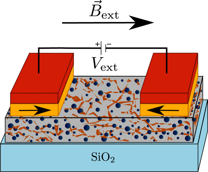
Figure 1. Schematic of the device geometry and nanocomposite composition.

The gray box represents the nanocomposite, with the blue spheres representing the iron-oxide nanoparticles and the brown strips representing the highly defective graphene oxide layers. The nanocomposite’s thin film is deposited on top of a silicon dioxide substrate (in light blue). Two cobalt ferromagnetic electrodes (yellow) are placed on top of the nanocomposite. For zero applied magnetic field, these are pinned in an anti-parallel configuration by PtMn layers (in red).
