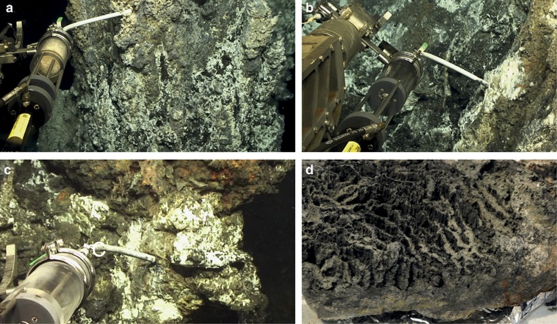
Figure 2.
Photographs showing (a) the sampling of ROV3, (b) the sampling of ROV4, (c) the sampling of ROV9 and (d) the flange structure, turned upside down, after arrival on the ship. The samples F1–F4 were subsamples of the flange, whereas the W1 sample was taken in the transition between the flange and the chimney wall.

