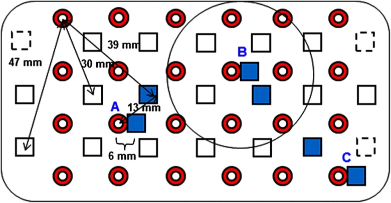
Fig. 1.
Fiber bundle geometry for light delivery (circles) and detection (squares). In the unmodified regions of the rectangular grid, nearest-neighbor source-detector spacings are 13 mm (S channels), but relocated detectors are placed 6 mm from sources at labeled locations , , and to provide three VS channels. The circle around location (radius 25 mm) indicates the zone of target channels considered “near to ” in the data analysis; see text for details. N.B.: view from back (convex side) of the near-infrared spectroscopy headpiece. Key: dashed squares—vacated detector gridpoints, shaded squares—selected detectors for S/VS comparison.

