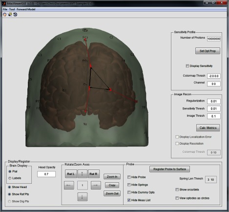
Fig. 4.
The result of registering the example probe to the atlas using the spring relaxation method. The depiction of the probe geometry indicates that the desired spacing was maintained within 3 mm between all source and detector positions (black color coding), while the springs connecting to anchor points are longer than their specified length by more than 10 mm (red color coding). Due to the use of unbalanced anchor points, the probe is positioned slightly to the right of the midline and has rotated slightly clockwise. By choosing different anchor points and/or adding additional anchors and springs, one can make minor adjustments to the probe positioning to get their desired positioning.

