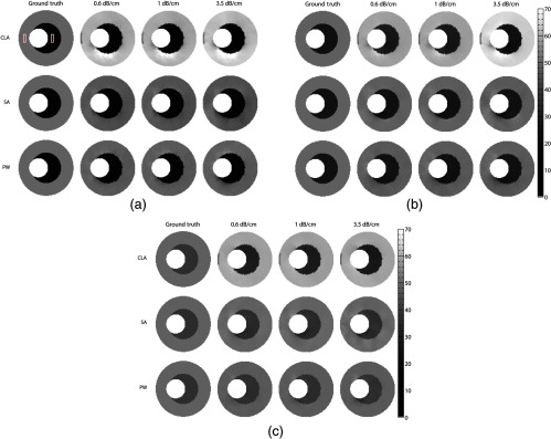
Fig. 6.

Montage of modulus elastograms, displayed in units of kilo Pascal (kPa), corresponding to the strain elastograms shown in Figs. 3 and 4. The first column of each montage shows the actual modulus elastograms and the remaining columns show the elastograms obtained from the simulated vessels with modulus contrasts of (a) , (b) , and (c) . Showing (a) conventional, (b) SA, and (c) PW modulus elastograms. The two rectangular boxes in (a) denotes the regions of interests corresponding to the simulated plaque and vessel wall that was used to compute values reported in Fig. 7.
