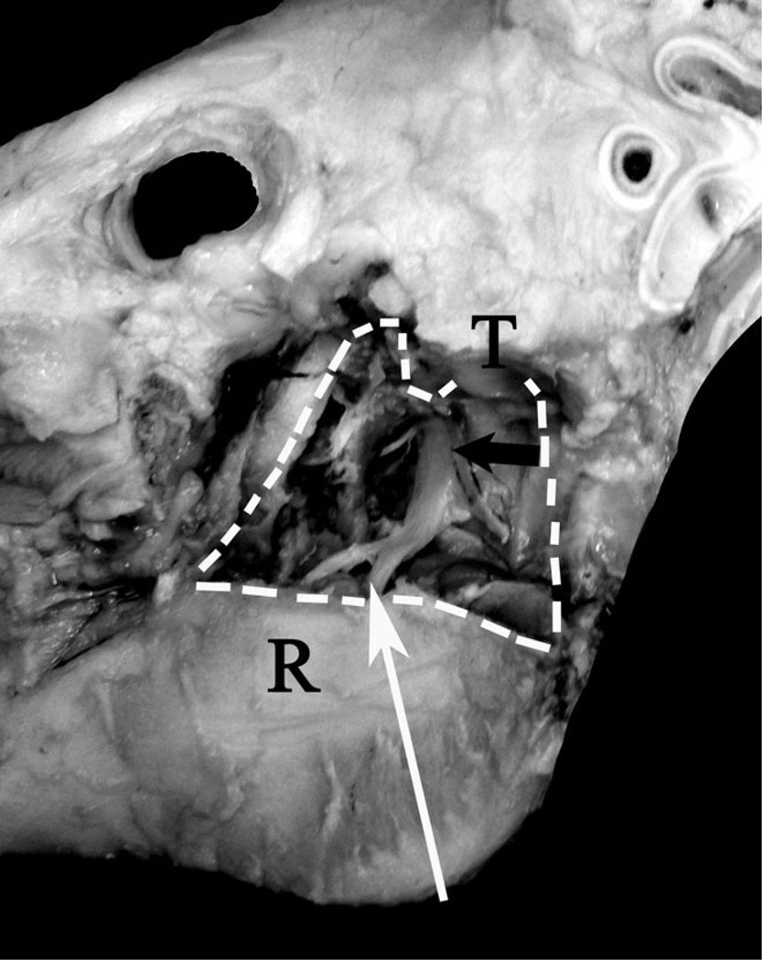
FIGURE 1.
Nerve stimulation and block technique. This dissection of a pig skull demonstrates the pathway of the mandibular nerve and the point at which the block is expected to be administered. The mandibular nerve (black arrow) runs cranial ventral from the foramen ovale toward the mandibular foramen. The needle attached to the electronic nerve stimulator was advance from the angle of the mandible toward the lateral canthus of the ipsolateral eye (white arrow) and medial to the ramus of the mandible. The white dotted line indicates the edges of the removed portion of the ramus (R). The temporomandibular joint is also labeled (T).

