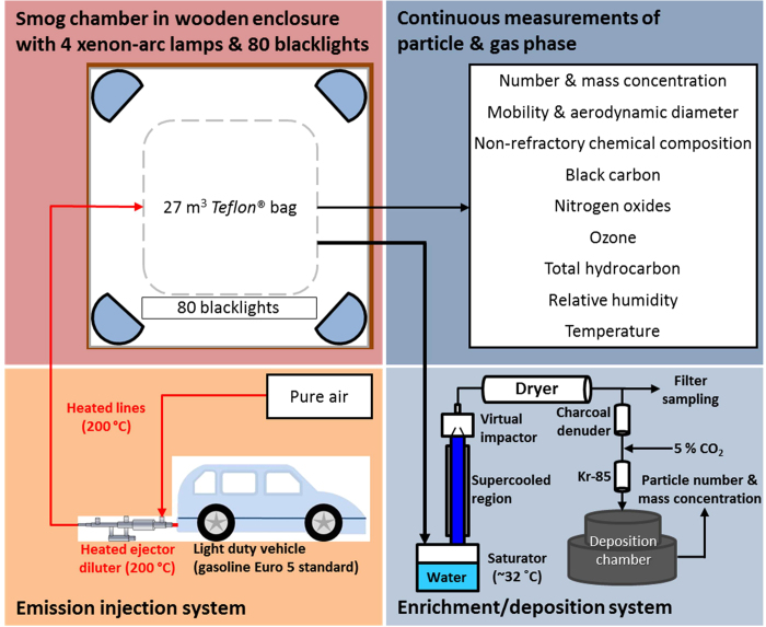
Figure 1. Schematic drawing of experimental set-up.
The bottom left panel (light pink) illustrates the injection system. Gasoline car exhaust was diluted with pure air and directly injected via heated lines (shown in red) into the smog chamber. The upper left panel (deep pink) shows the smog chamber, including 4 xenon-arc lamps (blue semi-circles) and 80 black lights. The upper right panel (dark blue) provides an overview of the parameters measured online during the experiment. The lower right panel (light blue) represents the particle enrichment system and the aerosol deposition chamber.

