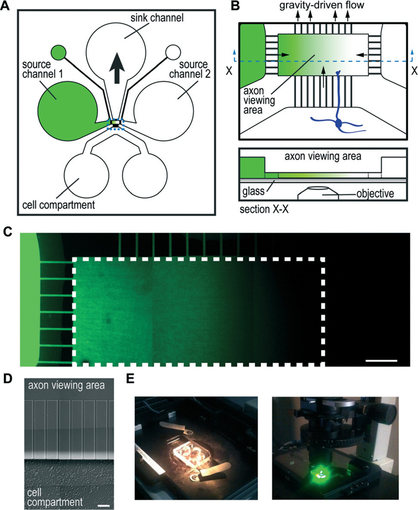
Fig. 1. Micro-pass gradient chamber.
(A) Cartoon illustration of micro-pass chamber and the channel layout. Source channels connect to a smaller outlet port to facilitate channel filling. Gradients are established by removing 30–45 µl from the sink well which draws in solution by gravitational force from the source channels/wells to create a gradient within the axon viewing area. (B) Illustration of the axon viewing area enlarged (top) and a profile view (bottom) showing that the axon viewing area and microgrooves are the same height (5 µm) and the source channels are taller (100 µm). (C) Representative fluorescence image montage of a low molecular weight dye gradient (AlexaFluor hydrazides) established within the micro-pass chamber. White dashed line outlines the axon viewing area. Scale bar, 100 µm. (D) Growth of mouse cortical neurons after 3 days within the chamber. Axons are present, but are not visible at this magnification. Scale, 50 µm. (E) Photographs of micro-pass chamber mounted on an inverted microscope. Photograph on the right shows the chamber within a humidified, temperature controlled, and CO2 adjusted stage incubator after 20 h of timelapse imaging.

