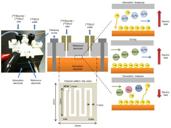
Figure 1.
(Left)Platinum-transition metal electrode cell assembled with fluidic and electrical connections.(Top center) Cross section of the flow cell. A patterned adhesive layer defining the fluid path (Bottom center) is sandwiched between an adsorption electrode and a reference electrode. Fluid follows a serpentine path to maximize the time spent within the electric field between the two electrodes. During trapping (top right), the negatively-charged [18F]fluoride ions are attracted to the positively-charged adsorption electrode and adsorb to the surface while the [18O]water continues to the outlet. (Middle right) [18F]fluoride is dried using an anhydrous solvent. (Bottom right) [18F]fluoride is released into a solution suitable for downstream radiochemical synthesis while applying a (generally smaller) reverse potential.

