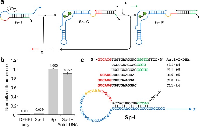
Figure 1.
RNA signal amplification circuit design. (a) Schematic illustration of the RNA signal amplifier mechanism. The circuit consists of three RNA strands: an internally blocked Spinach aptamer (Sp-I), a fuel strand (F), and a catalytic input strand (C). C hybridizes with Sp-I using the toehold (red) to form Sp-IC allowing the Spinach aptamer domain (blue) to fold and activate fluorescence after binding DFHBI. Subsequently, F hybridizes with Sp-I via the newly exposed toehold (green) to displace C which can engage in further catalysis. (b) Fluorescence of Sp and Sp-I (500 nM) in the presence of DFHBI (3 μM). Fluorescence of Sp-I was restored in the presence of Anti-I-DNA (1500 nM). The average raw fluorescence values from triplicate experiments were obtained and normalized by the corresponding fluorescence of Sp (500 nM). (c) Sequences of the circuit components described in this work.

