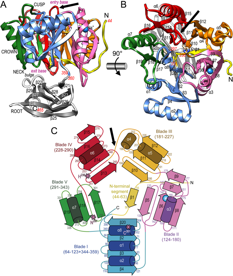
Figure 1. Overall structure and topology of PPAD.
(A) Ribbon-type plot of PPAD in a lateral view revealing its tooth-like shape, which consists of regions assignable to cusp, crown, neck and root. The upper N-terminal cylindrical catalytic domain (CD; residues 44–359; top entry base and bottom exit base) is shown with the N-terminal segment in yellow and each of its constituting blades (I to V) in one color (blue, magenta, orange, red, and green). The C-terminal IgSF-like domain (residues 360–465) is shown in grey for its β-strands (labeled β22-β29) and white for loops and coils. A sodium ion is shown as a blue sphere and a black arrow pinpoints the Michaelis-loop. (B) Top view onto the entry base of the CD cylinder after a horizontal 90°-rotation of (A). The helices (α1-α8) and strands (β1-β20) of the CD are labeled. Catalytic-triad-residue (C351, H236 and N297) side chains are shown and labeled in red to highlight the active site in the center of the α/β-propeller. A black arrow pinpoints the Michaelis-loop. (C) Topology scheme of the five-bladed PPAD CD with strands as arrows and helices as cylinders with their respective limiting residues; coloring as in panels (A) and (B). The three catalytic residues of (B) are shown as pink asterisks, and the Michaelis-loop is denoted by a black arrow.

