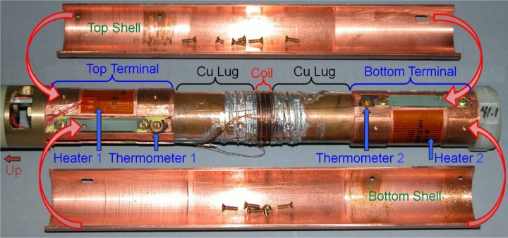
Fig. 12.
Picture of exploded view of the lower part of the variable temperature only (VTO) probe. The test fixture is bolted between the top and bottom terminals. In operation, the left direction is up. Each terminal has a thermometer and heater. The top and bottom copper shells are two halves of a cylinder. Follow the assembly arrows from the shells to the terminals to see how the two shells fit around the test fixture and terminals.

