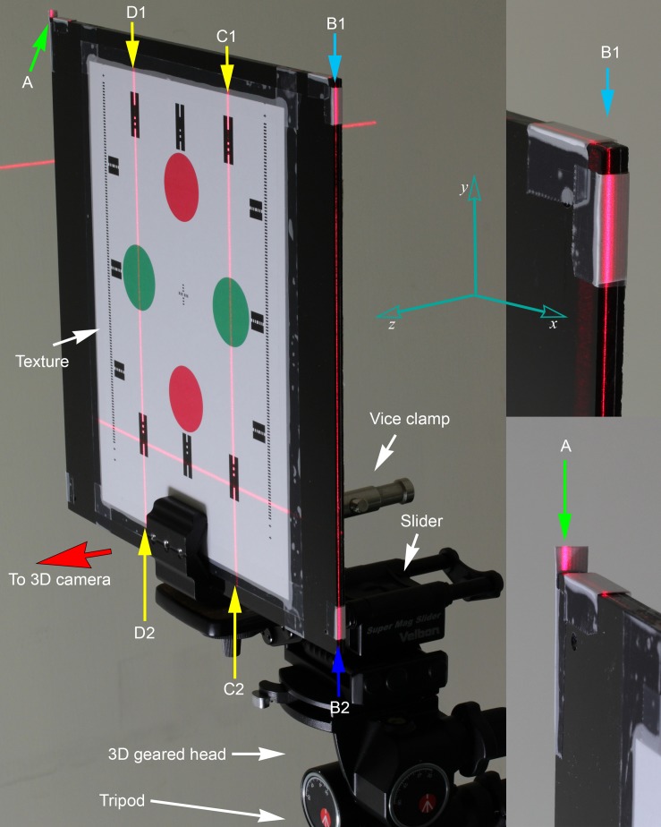
Fig 2. Set up of the reference board.
The reference board was taped with color patterns on the front side facing the SP device cameras. Side grooves were crafted by using surface gauge at the side and top edge. Short paper tags were taped near the edges for angulation matching with laser beams. It was held by a vice clamp, connected to a two-way focusing slider for fine horizontal positional adjustments; and 3D geared head for angulation adjustments. Laser beams A (bottom right) and B1–B2 were projections from V2 which was aligned to be parallel to the mirror plane. Laser beam C1–C2 and D1–D2 were projections from front alignment lasers. Yaw angle was aligned with A-B1 (right) and top board edge; pitch angle was aligned with B1–B2 and side groove; roll angle was aligned with C1–C2, D1–D2 and dotted lines on card paper.

